Major upgrade with M5StickC Plus2! Building a Simple Bipedal Robot Part 10
Toon Robotics is supported by its audience. When you purchase through links on my site, I may earn an affiliate commision.
Previous Development
Previously, I created and successfully completed Ver. 2.1 with color printing.
Plans for further upgrades
I have created a new model called Ver. 2.1 last time, but here I got a little greedy.
I want to make a version with a little more performance.
For example, it can detect posture to prevent tipping over, check the status on the display, make a sound, perform more complicated calculations, etc.
It is possible to add some sensors to Ver.2.1, but it may require complicated wiring and trial and error for installation position.
I was doing some research with this in mind, and this is what I found!
M5StickC Plus2 on eBay
It is a relatively small version of the famous M5Stack series, but it is equipped with an IMU (Inertia Measurement Unit), a display, a buzzer, a microphone, and so on. There are smaller versions, but this one seems to be just right, as it has a lot of stuff.
And the timing seems good, as it has just been updated from the M5StickC Plus.
The ESP32-PICO-V3-02 has more computing power than the Raspberry Pi Pico, and has more RAM, Flash, etc., so you can do a lot of things with it. The price is also higher, though…
So I will create an upgraded version with M5StickC Plus2.
Keep the parts that can be diverted.
However, the body part of the system is fully operational up to Ver. 2.1, so the things that needs to be changed are
- Change of circuits and sensors to be used
- Internal circuit storage area
However, since the timing is just right, we will make the parts that required painting into an assembly type so that painting is not necessary. Servo motors and batteries are the same as before.
The servo motor control board and ultrasonic sensor will be changed, and the ultrasonic sensor will be Grove-compatible because GPIO pins are limited and Grove pins must be used efficiently.
I use this for the servomotor control board.
Adafruit 16-Channel 12-bit PWM/Servo Driver – I2C interface – PCA9685
Ultrasonic sensors are here.
https://wiki.seeedstudio.com/Grove-Ultrasonic_Ranger
Internal Design
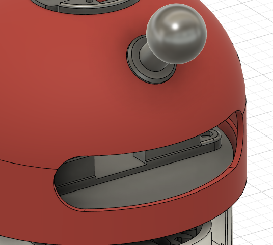
Now let’s make the internal part that houses these circuits and the part that holds the sensor in place.
This is what it looks like.
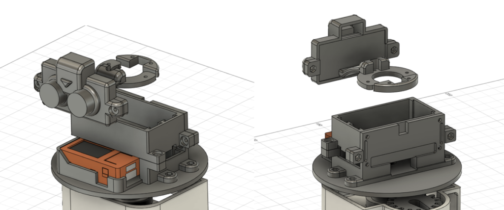
All other parts will use the previous version without modification.
Printing! Assembly!
Now let’s print it out.
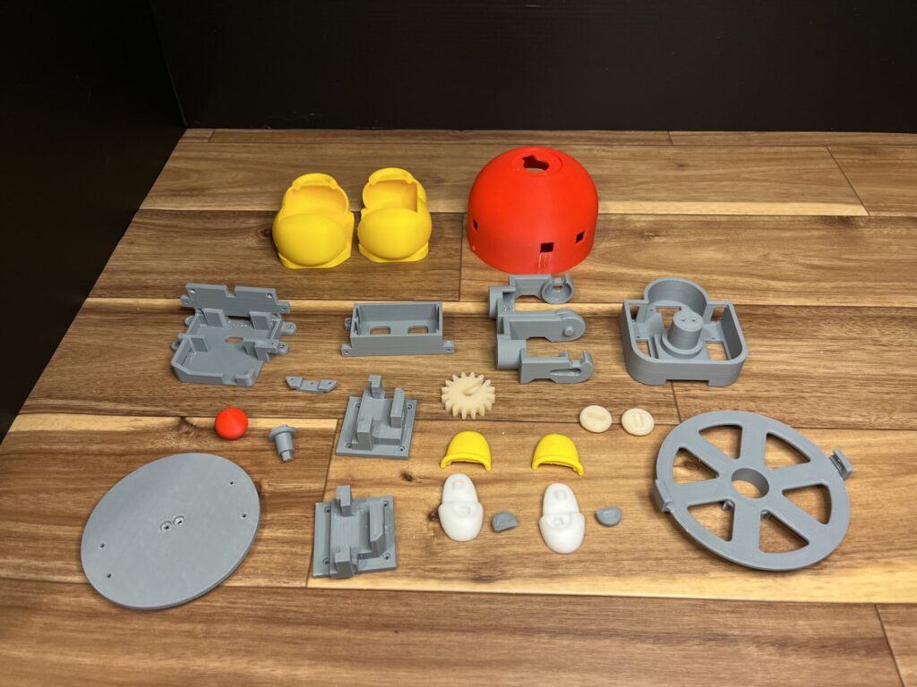
I wanted the pupils to be black, but there was no black filament available, so I printed them in gray. I will paint this one a little later.
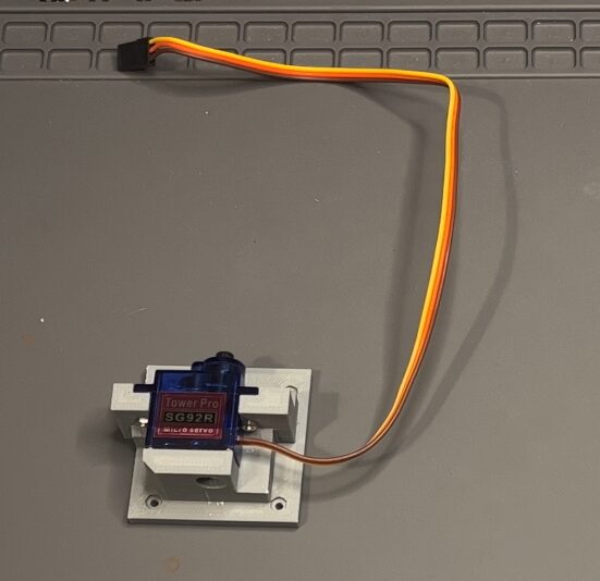
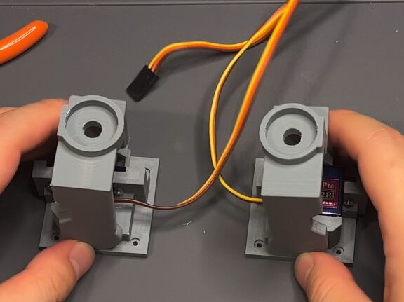
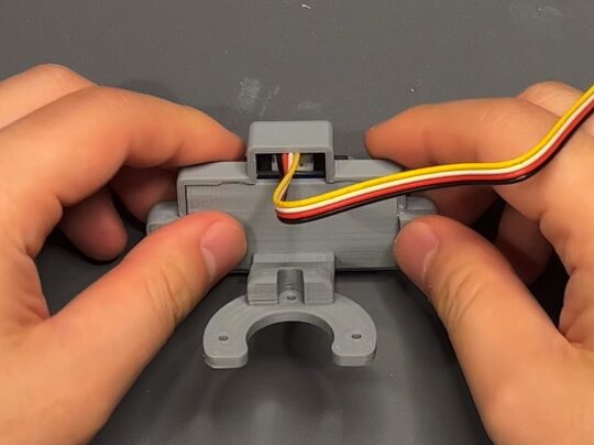
Now, let’s assemble, assemble, assemble. The legs come first.
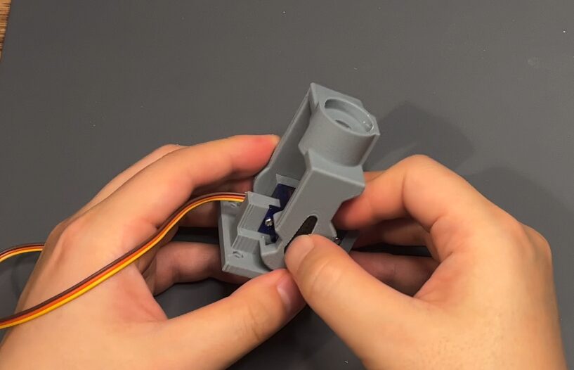
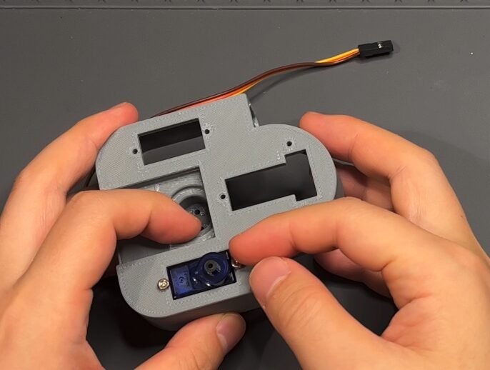
Next is the body section.
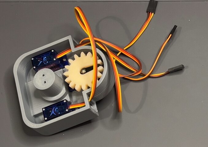
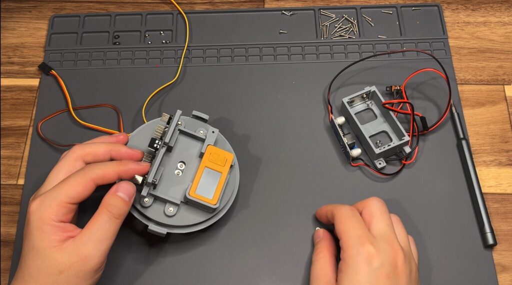
Next is the internal circuit.
M5StickC Plus2 also fits perfectly.
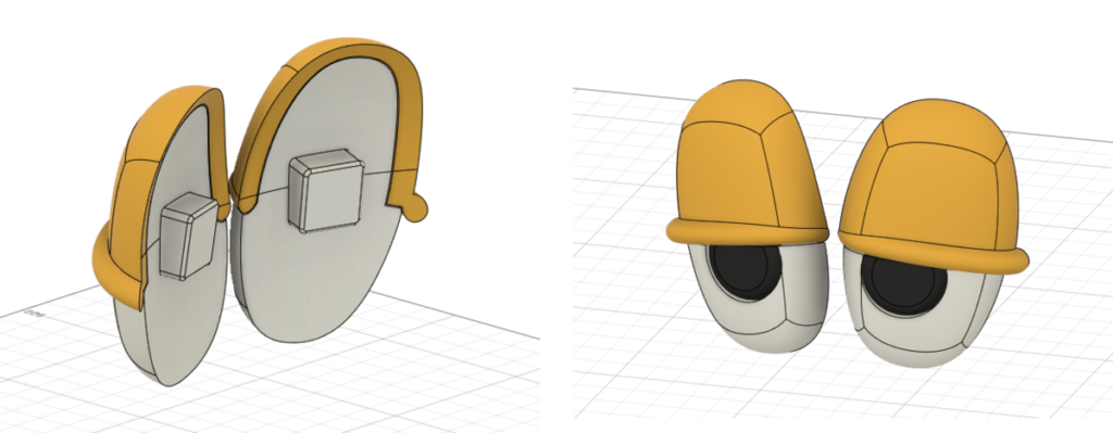
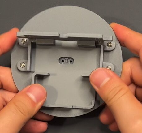
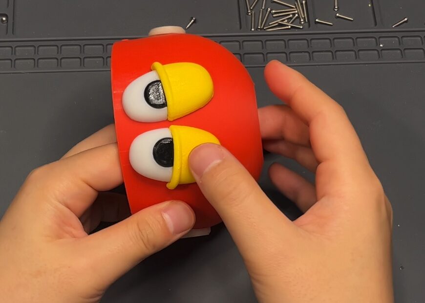
The new eyeballs were also assembled…
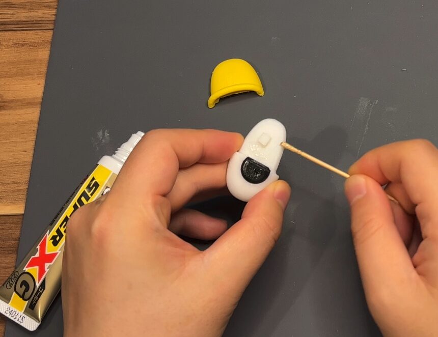
The painting is no longer necessary since it is now assembled.
An ultrasonic distance sensor is also installed…
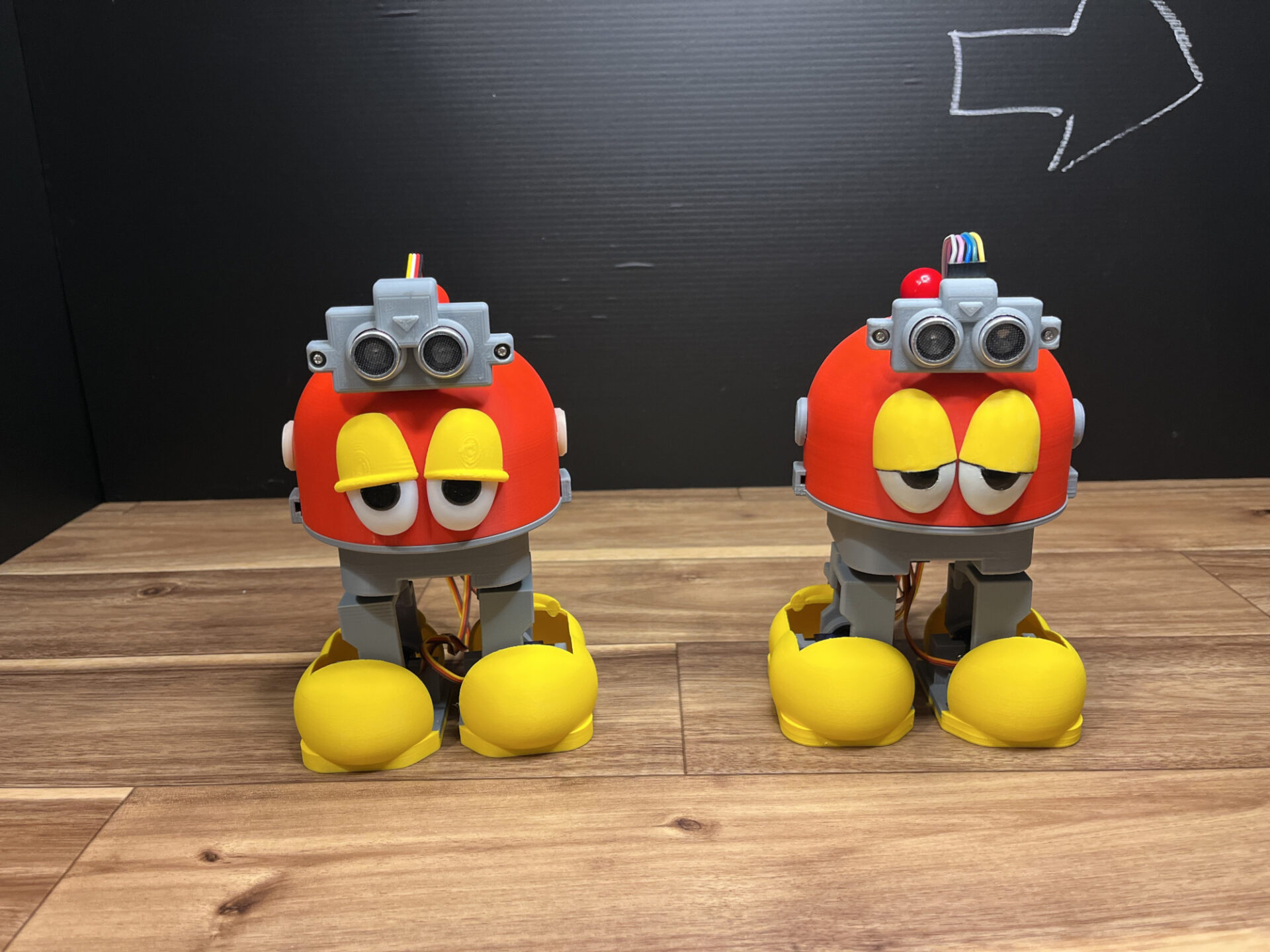
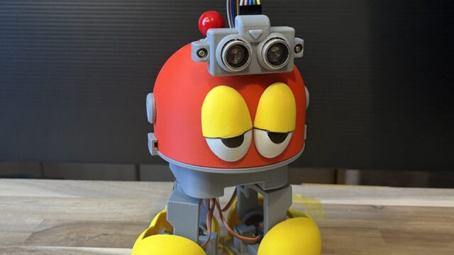
And somehow… it’s done.

There are only a few visual differences, but the internals have been significantly upgraded. It also works well.
Next
In the next article, I will introduce the internal circuitry and other new features.
For the latest status, check here.