Easy to Print and Assemble Mecanum Wheels! – Experiments and Verifications
Toon Robotics is supported by its audience. When you purchase through links on my site, I may earn an affiliate commision.
Introduction
This article examines the performance of the easy to print and assemble Mecanum wheel, as described in a separate article.
If you haven’t read the other article yet, please read it first.
Let’s examine the difference in performance depending on the grip of the roller.
Previous article explained how to make a mecanum wheel with a 3D printer and assemble it. It also mentioned that certain floor surfaces may need more grip.
The main options were processing with heat shrink tubing and printing with TPU. The approximate gripping performance is as follows.
TPU ≈ heat shrink tubing processed PLA > PLA
This article describes the experiments to verify performance.
I will actually conduct an experiment using the mecanum wheel with a robot car for verification. For more detailed information on the operation of mecanum wheels, please refer to this article.
Experimental Settings
Robot car for experiments
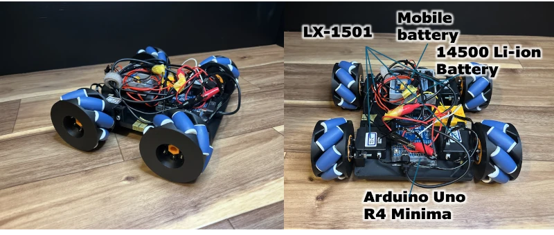
I created a simple robot car for verification (Figure 1 and 2). I used a servo motor LX-1501 by HiWonder to turn the wheels. The servo motor is in motor mode (continuous rotation). It is controlled by an Arduino Uno R4 Minima and powered by a mobile battery and a lithium-ion battery.
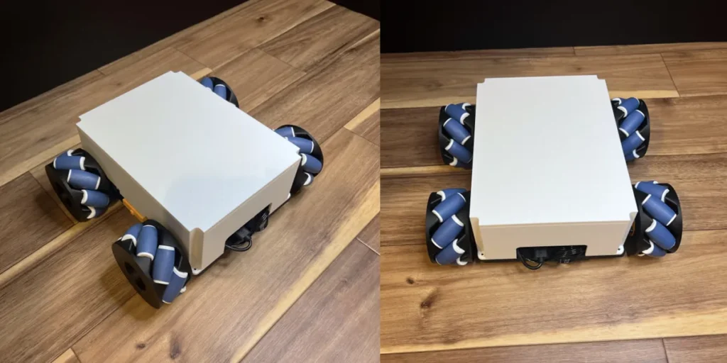
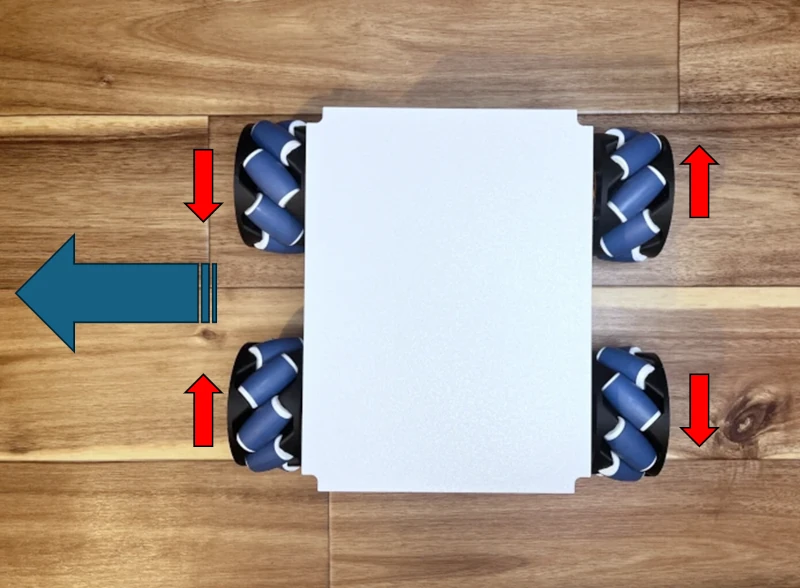
In this experiment, I will verify the movement of the mecanum wheel, an omni-directional wheel, by moving it sideways. The wheel movement shown in Figure 3 enables the realization of lateral movement.
Various rollers and mecanum wheels
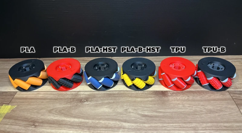
In this experiment, I will create and compare six different rollers. Specifically, the six types are:
- MMade of PLA (PLA)
- Made of PLA with bumpy surface (PLA-B)
- Made of PLA with heat shrink tubing processing (PLA-HST)
- Made of PLA with heat shrink tubing processing and bumpy surface (PLA-B-HST)
- Made of TPU (TPU)
- Made of TPU with bumpy surface (TPU-B)
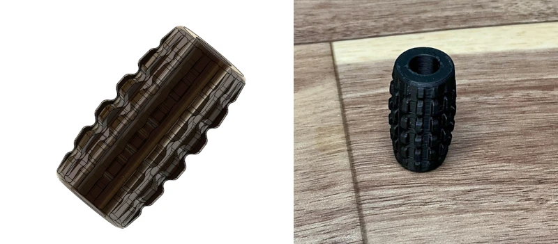
HST is an acronym for Heat Shrink Tubing. Rollers with bumpy surfaces are also available for each for verification purpose (Figure 4).
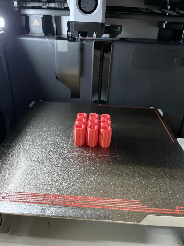
Six types of rollers are available: PLA, heat-shrink tubing processed PLA, and TPU (Figure 5), each with an uneven roller.
Please refer to the previous article for the processing method using heat-shrink tubing.
I did all my printing on Bambu Lab X1 Carbon. Also, the filaments used in this experiment were PLA and TPU.
I also used a filament dryer for printing TPU.
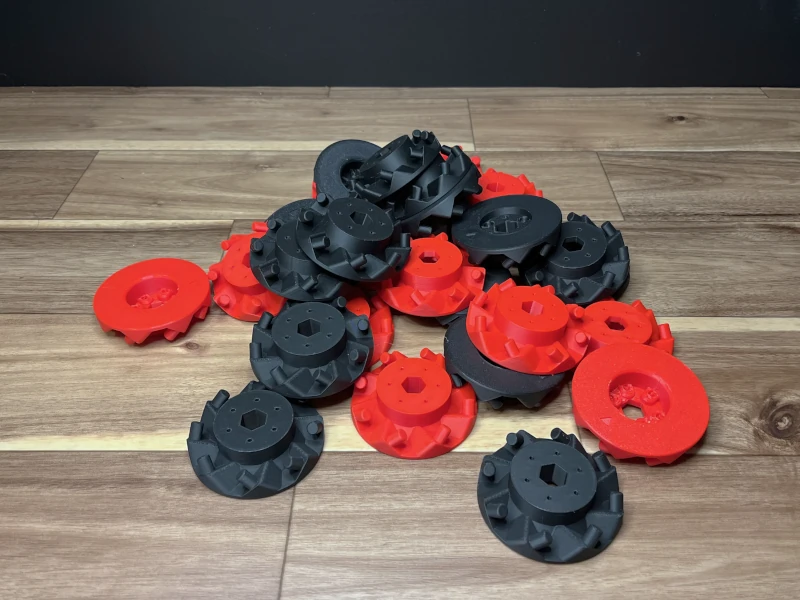
All six types of mecanum wheels are available (Figures 6 and 7). There is no difference by color.
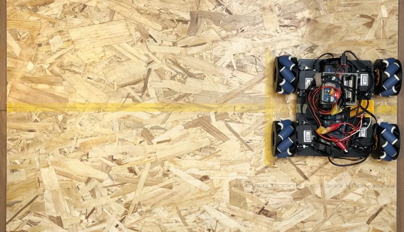
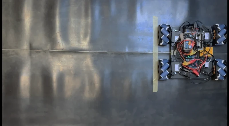
Experimental Field
I prepared two floor surfaces with different friction for the experimental field. One is plywood board (Figure 8) as a relatively slippery and smooth floor surface, and the other is a rubber mat with high friction (Figure 9).
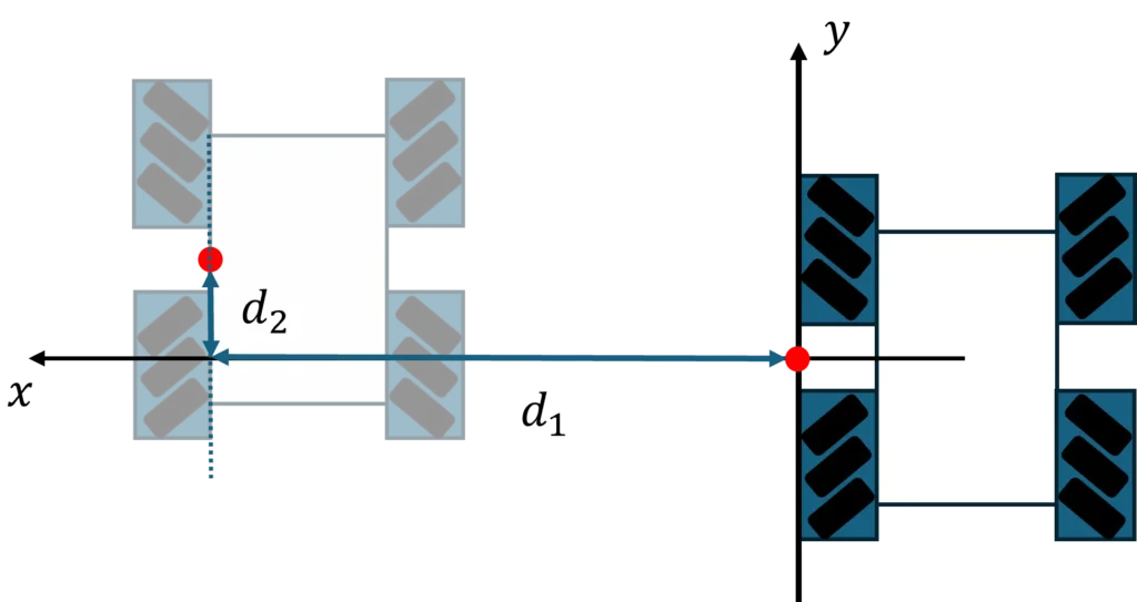
Experimental Settings
Next, set up the experiment. The robot car rotates the wheels for 3 seconds and measures the distance traveled. In Figure 10, distances \(d_1\) and \(d_2\) are measured. If the roller rotates properly, \(d_2\) is zero and \(d_1\) is larger.
Five experiments will be conducted on each of the six types of wheels, and the results will be analyzed.
Results
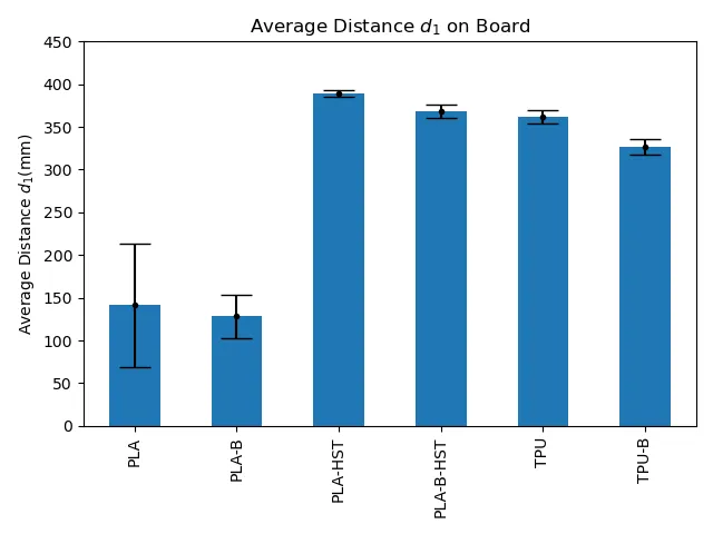
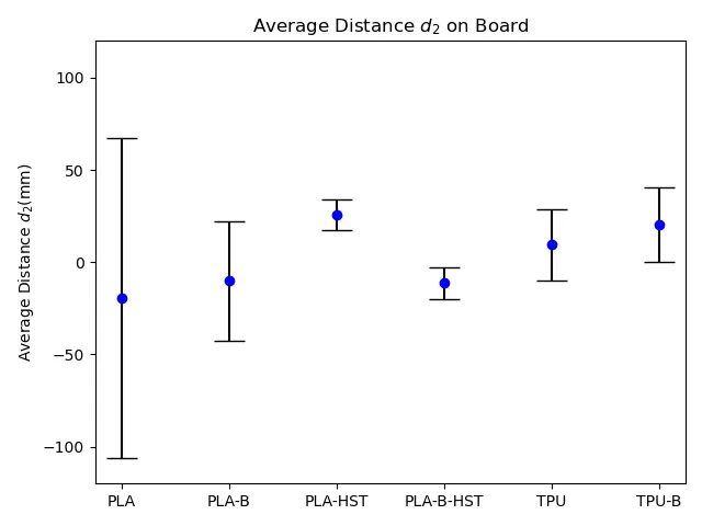
Let’s review the experimental results. Plywood board results are displayed in Figure 11 for \(d_1\) and Figure 12 for \(d_2\). The vertical axes show \(d_1\) and \(d_2\) values from 5 trials in mm. The error bars represent standard deviations, showing more variation with larger bars.
Figure 11 illustrates that the PLA rollers without processing have poor movement because of insufficient grip (PLA, PLA-B). The error bars show these rollers are unstable with significant variation.
In contrast, the rollers processed with heat shrink tubing exhibit less variation and stability and can move a specific distance (PLA-HST, PLA-B-HST).
The results from the latter experiment on the rubber mat show that the maximum distance of \(d_1\) is around 400 mm. This means that PLA-HST can move almost as far as on a high-friction floor. There is no notable difference between TPU and PLA-HST, showing TPU is also working effectively.
On the other hand, bumpy surface had no significant or slightly adverse effect on performance (PLA-B, PLA-B-HST, TPU-B).
By looking at Figure 12, we can see the magnitude of variation in each case. Processing with heat shrink tubing is stable (PLA-HST, PLA-B-HST). TPU is also stable (TPU, TPU-B), but with some differences.
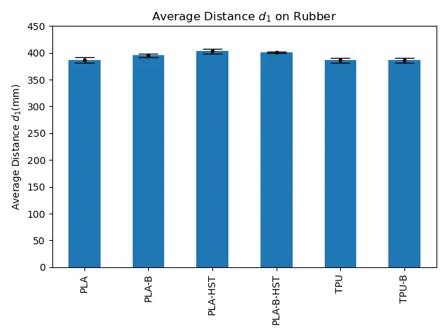
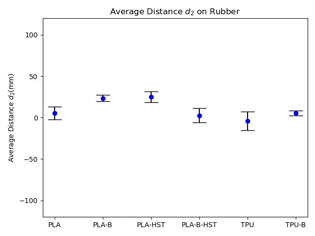
The following results are for rubber mats. Figure 13 shows the results for \(d_1\), and Figure 14 shows the results for \(d_2\). The floor surface has high friction, so we can expect good performance even with just the slippery PLA material. Let’s now examine the actual results.
We can observe from Figure 13 that there is hardly any difference in results among the six types, and the variation in results is minimal. The best result of PLA-HST is about 400 mm. The other results didn’t show any performance difference.
We can conclude that the maximum limit of (d_1) in this setup is around 400 mm.
From Figure 14, both the variation and the value of \(d_2\) are small. All six types of rollers function without problems on a floor surface with high friction.
Conclusion
In summary,
PLA rollers are available for high-friction floor surfaces with no further treatment.
Conversely, heat shrink tubing processing provided the best results on slippery floors. The performance of TPU rollers was satisfactory, with no significant difference noted in comparison.
If a more flexible material or a material with higher friction than the current TPU material is used, it is possible to achieve enhanced performance.
Thus, the gripping performance is outlined as follows.
TPU ≈ Heat shrinkable tubing processed PLA > PLA
Thus, for slippery surfaces with low friction, use a roller with heat shrink tubing or TPU material.
Both options work similarly, so choose the easier one to make.
We discovered that the bumpy surface rollers did not affect performance. Therefore, they are not part of the “Easy to Print and Assemble Mecanum Wheel” data set.
For the latest status, check here.