Automate ultrasonic distance sensor US-100 with interrupt timer! (Arduino Leonardo and Raspberry Pi Pico Version)
Toon Robotics is supported by its audience. When you purchase through links on my site, I may earn an affiliate commision.
Topics
This article describes an easy-to-use software module and sample of the US-100 ultrasonic distance sensor using an interrupt timer and how to use it.
If you know about ultrasonic distance sensors, read on from here.
Click here to view the source code and how to use it.
US-100 ultrasonic distance sensor
What is an ultrasonic distance sensor?
In robotics and electronics, there are times when you want to measure the distance to an obstacle. In such cases, distance sensors are useful. There are two types of distance sensors: optical sensors that use lasers and ultrasonic sensors that use ultrasonic waves. Each type has its own advantages and disadvantages, but let’s use an ultrasonic distance sensor this time.
US-100 and HC-SR04
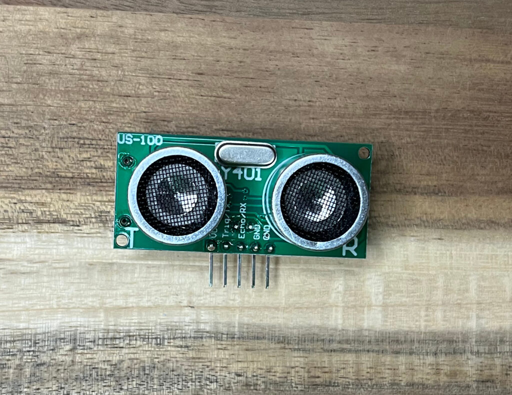
The ultrasonic distance sensor used in this article is the US-100 (Figure 1). A similar one is HC-SR04.
The sales websites are as follows.
ebay
https://ebay.us/IiCYnM
↑US-100
https://ebay.us/1t8s9L
↑HC-SR04
The HC-SR04 was originally a fairly well-known ultrasonic distance sensor, and the US-100 is an even more convenient handling from it.
UART mode and UART
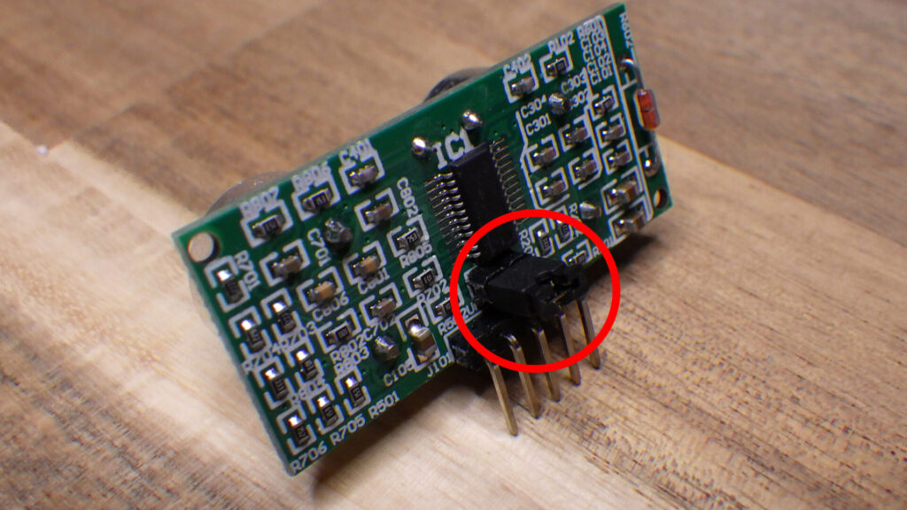
The US-100 has two modes. Serial UART mode and HC-SR04 mode. If you remove the jumper on the back, it acts as HC-SR04 mode. As the name suggests, HC-SR04 mode works just like HC-SR04. This time, however, I will use the more convenient Serial UART mode.
UART stands for Universal Asynchronous Receiver-Transmitter, which is an asynchronous serial communication method often used in Arduino and other devices. Some sensors use synchronous serial communication such as I2C or SPI when exchanging complex data, but the US-100 uses simple UART communication.
Common usage and its problems
When using HC-SR04, the voltage on the connecting pin must be measured directly to measure the timing. An ultrasonic distance sensor first generates ultrasonic waves, which are reflected by an obstacle, and measures the distance based on how long it takes for the reflected sound waves to be input to the microphone. HC-SR04 needs to manage this process tightly.
On the other hand, the US-100’s serial UART mode automatically performs such processing and allows direct retrieval of pre-calculated distance data.
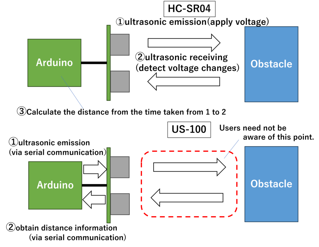
In the case of US-100, there is no need to implement the measurement part, and the distance measurement is completed only by serial communication.
This time, I will assume that I will use the Arduino IDE to run on an Arduino Leonardo and a Raspberry Pi Pico.
First, let’s look at the general procedure for using the HC-SR04.
1. Using pulseIn()
The simplest method is to use pulseIn(). pulseIn() is a function that detects a change in voltage on a specified pin and measures the time until the voltage changes. This allows us to measure the time between the emission and reception of ultrasonic waves, as shown in the figure above in Figure 3. The distance to the obstacle can then be determined by calculating the distance from the sound speed value. However, pulseIn() causes “blocking” that stops other processes during the measurement.
2. Using interrupt processing
The next most commonly used method is to use interrupt processing. “Interrupt” processing is essential in embedded systems. An interrupt is a process that halts the current operation and literally “interrupts” it to perform another process in response to a change in state.
By making the ultrasonic measurement an interrupt process as described here, you can measure the distance without stopping other processes. This method can be executed without stopping other processes and is considered to be accurate, but you have to manage the timing of measurement and re-measurement after reception by yourself.
In the US-100’s UART mode, everything is completed by serial communication with the US-100 itself, so you can use it without being aware of this. Adafruit introduces PingSerial for use. This library supports use in UART mode.
However, even when this is used, the measurement timing must be managed by the user. If this timing management is in the main loop(), it is very complicated when combined with other processing.
So this time I would like to automate the measurement so that it will periodically take measurements at regular intervals and I can read them out at any time I wish. In this case, the measured distance will always be updated at regular intervals, so that in the main loop() I can simply read it out at any desired timing.
Using timer interrupt
There is a mechanism called “timer interrupt” that can generate interrupts at regular intervals by using the hardware timer on microcontroller boards such as Arduino.
This generates an interrupt at regular intervals, which is more accurate than software time management. If we can use this timer interrupt to allow the US-100 to take measurements at regular intervals, we should be able to treat it as a distance sensor whose information is updated periodically.
For many boards, hardware timers are a valuable resource, so I do not want to waste them carelessly. Therefore, I will use this library.
This library allows multiple timer interrupts to be generated for a single hardware timer and also reduces the complexity of dealing directly with hardware timers.
Software module for US-100 with timer interrupt (Available on Github!)
Let’s get right to the point. I have created and uploaded a module for US-100 that uses timer interrupt. You can download it from here!
I am assuming use with Arduino Leonardo and Raspberry Pi Pico, but other boards can basically be used as long as the necessary pins are connected and their support is available.
Arduino Leonardo: https://ebay.us/gIOBQ8
Raspberry Pi Pico: https://ebay.us/KnLph1
Let’s take a look at how to use it below, and click here for the Raspberry Pi Pico version.
Arduino Leonardo ver.
Connection
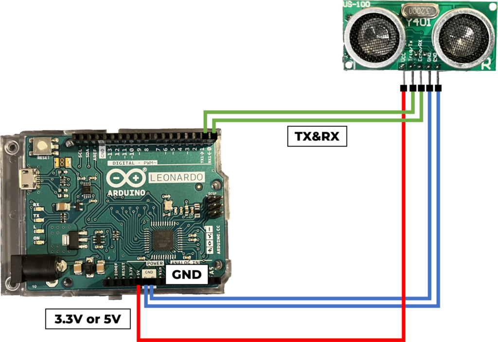
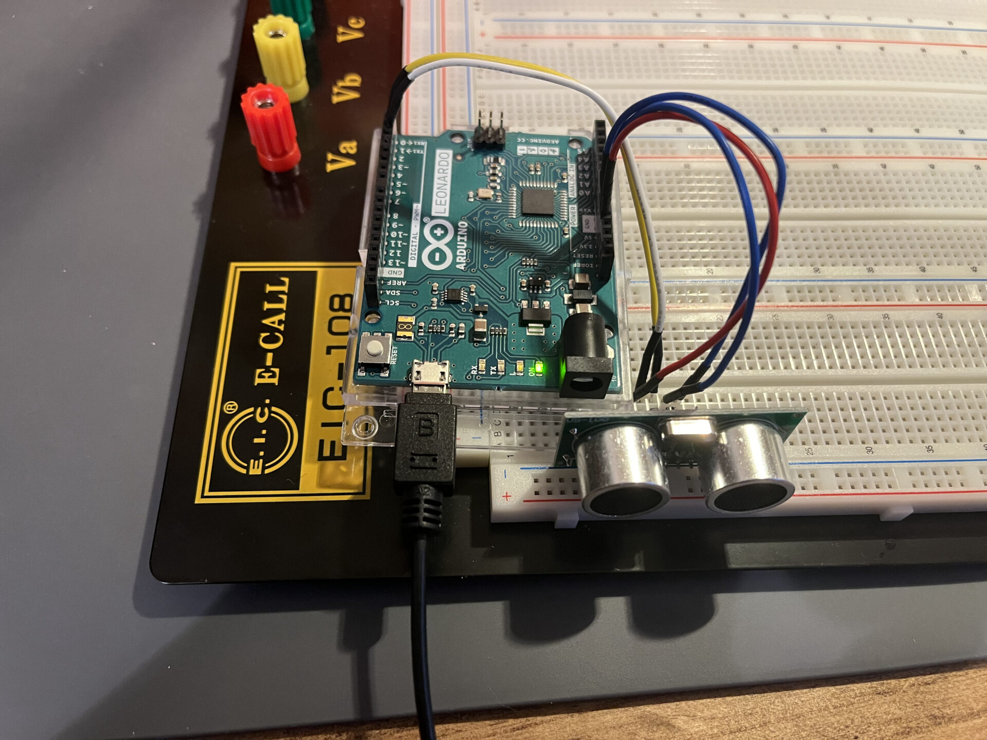
First, connect the US-100 to the Arduino Leonardo as shown in Figure 4.
- 3.3V or 5V pin of Arduino Leonardo and VCC pin of US-100
- GND pin of Arduino Leonardo and GND pin of US-100
- DIGITAL 0 pin of Arduino Leonardo and Echo/RX pin of US-100
- DIGITAL 1 pin of Arduino Leonardo and Trig/TX pin of US-100
US-100 supports input voltages from 3V to 5V, so either 3.3V or 5V VCC is acceptable. Connect GND, then RX and TX for UART to their corresponding pins. DIGITAL0 and 1 on the Arduino Leonardo are also labeled RX1 and TX1, respectively, in small letters.
Next, open the sketch file TimerDrivenUS-100.ino in the Arduino IDE. Also, check that the files US100.h and US100.cpp are in the same directory.
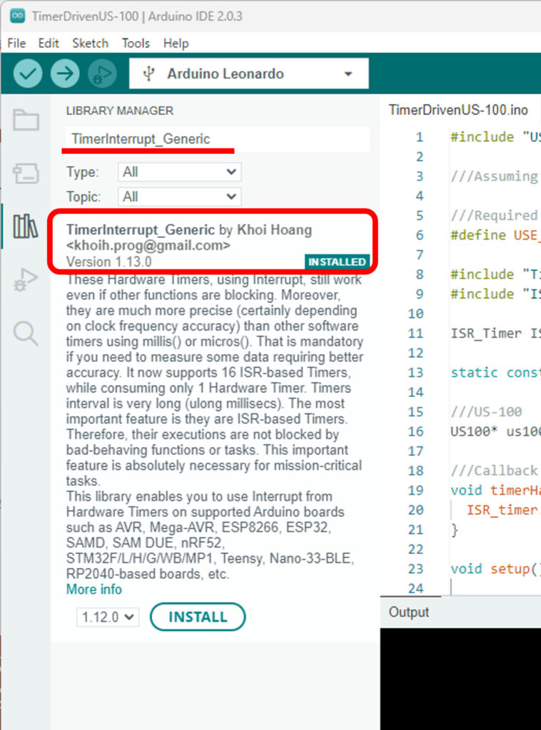
Install the library “TimerInterrupt_Generic” as shown in Figure 5. If it is not installed, install it. The version is 1.13.0 at the time of writing (2023/10/2).
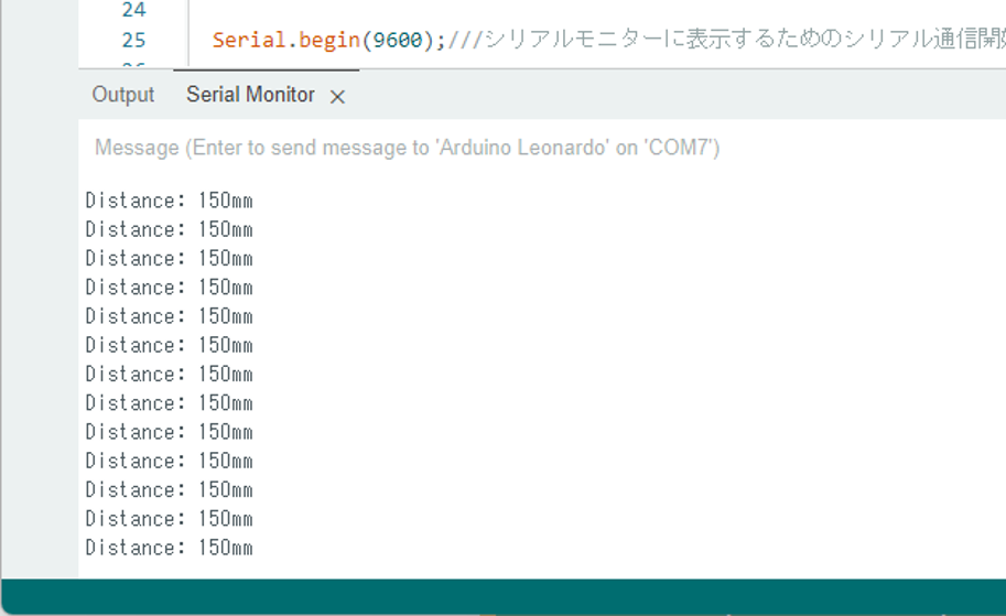
All that remains is to write this sketch. After starting up, try activating the serial monitor. Then, if you have done it correctly, you should see something like Figure 6, and you will see this distance change as you place obstacles in front of the US-100.
Let’s take a look at the actual source code of TimerDrivenUS-100.ino.
First, let’s start before setup().
#include "US100.h"

///Assuming Arduino Leonardo

///Required to use timer
#define USE_TIMER_3 true

#include "TimerInterrupt_Generic.h"
#include "ISR_Timer_Generic.h"

ISR_Timer ISR_timer;///ISR Timer

static const unsigned long HARDWARE_TIMER_INTERVAL_MS = 5UL;

US100 us100(20,4500);///US-100. Arguments are minimum and maximum distance (default values will be set if not specified).

///Callback function for hardware timer to use ISR timer.
void timerHandler(){
  ISR_timer.run();
}
So far, these are the settings required to use the timer. If you are not familiar with this, just write this down and you should be good to go.
For details, see the TimerInterrupt_Generic sample code, but it is worth noting that the callback function timerHandler() for hardware timers is provided.
US100 stores an instance of the US-100 management class provided in US100.h and US100.cpp.
What can be set here are the minimum and maximum measurement distances for US100. If not set, the default values of minimum distance of 100 mm and maximum distance of 2500 mm are set, but in this case, I will set them at 20 mm and 4500 mm.
According to Adafruit
They work at about 2cm to 450cm away, but we think 10cm-250cm will get you the best results.
and that it should work between 20mm and 4500mm, but is more effective when used between 100mm and 2500mm. In this case, I will use 20mm to 4500mm. If a value outside this range is observed, we assume the value is invalid and return “0″.
Now let’s take a look at setup().
void setup() {

  Serial.begin(9600);///Start of serial communication for display on the serial monitor

  us100.setup();///Set up the US-100

  ITimer3.init();///Initialize hardware timer

  // Set hardware timer for ISR timer execution (see TimerInterrupt_Generic sample code).
  if (ITimer3.attachInterruptInterval(HARDWARE_TIMER_INTERVAL_MS, timerHandler))
  {
    Serial.print(F("Starting ITimer3, millis() = "));
    Serial.println(millis());
  }
  else{
    Serial.println(F("Can't set ITimer3. Select another frequency or a timer."));
  }

  ///Set ISR timer execution interval and a callback function.
  ISR_timer.setInterval(US100::TIMER_INTERVAL_MS, US100::ISR_timerHandler, &us100);

}
Here, serial communication is started for the display. Next, setup() of US100 is executed, and serial communication is also started separately. The ISR timer call interval, i.e., the measurement interval on US-100, is set to 100 ms.
Once you get this far (if you don’t know what you’re doing, just write it as is and it will work) Then all that is left is to use it in loop().
void loop() {

  int dist = us100.getDistance();

  Serial.print("Distance: ");
  Serial.print(dist);
  Serial.println("mm");

  delay(100);

}
In this sample, getDistance() is used to receive distance information from US-100 every 100ms and display it. In this way, it can be used without worrying about timing management at all. Also, since timer interrupts are used, distance measurement can be performed more accurately without being affected by processes such as delay() that stop other operations during loop().
Raspberry Pi Pico ver.
Connection
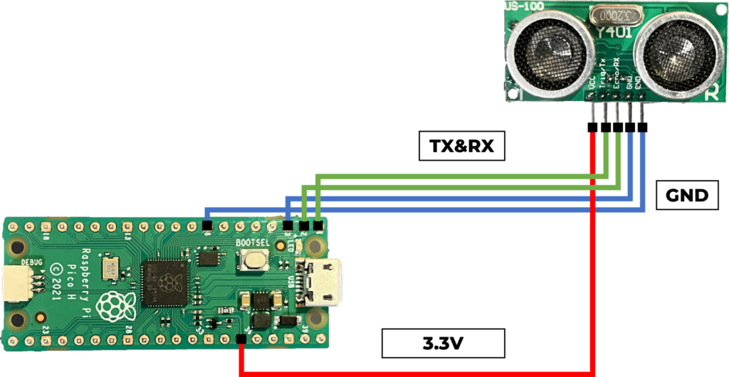
Now let’s look at using the US-100 with the Raspberry Pi Pico. Connect as shown in Figure 7.
- 3.3V(3V3(OUT)) pin of Pi Pico and VCC pin of US-100
- GND pin of Pi Pico and GND pin of US-100
- GP 1(UART0 RX) pin of Pi Pico and Echo/RX pin of US-100
- GP 0(UART0 TX) pin of Pi Pico and Trig/TX pin of US-100
Connect VCC to 3.3V, GND to GND, and RX and TX for UART to their corresponding pins to complete the wiring.
Next, open the sketch file TimerDrivenUS-100ForPiPico.ino in the Arduino IDE. Make sure you also have the files US100.h and US100.cpp in the same directory.
As with the Arduino Leonardo, the library TimerInterrupt_Generic should also be installed.
All that remains is to upload this sketch.
Let’s look at just the main changes from the Arduino Leonardo version of the source code.
#include "US100.h"

#include "TimerInterrupt_Generic.h"
#include "ISR_Timer_Generic.h"


MBED_RPI_PICO_Timer ITimer(0);///for pico
ISR_Timer ISR_timer;

static const unsigned long HARDWARE_TIMER_INTERVAL_US = 10000UL;///for pico
First of all, the timer settings are different from the Arduino Leonardo version. The hardware timer interval is also changed from milliseconds to microseconds.
The timer handler is also written slightly differently.
void timerHandler(uint alarm_num){

  TIMER_ISR_START(alarm_num);///for pico

  ISR_timer.run();

  TIMER_ISR_END(alarm_num);///for pico
}
After this, setup() is only slightly different.
void setup() {

  Serial.begin(9600);

  us100.setup();

  if (ITimer.attachInterruptInterval(HARDWARE_TIMER_INTERVAL_US, timerHandler))///for pico
  {
    Serial.print(F("Starting  ITimer, millis() = "));
    Serial.println(millis());
  }
  else{
    Serial.println(F("Can't set ITimer. Select another frequency or a timer"));
  }

  ISR_timer.setInterval(US100::TIMER_INTERVAL_MS, US100::ISR_timerHandler, &us100);

}


void loop() {

  int dist = us100.getDistance();
  Serial.print("Distance: ");
  Serial.print(dist);
  Serial.println("mm");

  delay(100);

}
Note
1. The measurement interval can be changed from 100 ms by changing TIMER_INTERVAL_MS in US100.h.
2. The US-100 can also measure temperature, and this code can also measure temperature. us100.requestTemperature() can be executed in advance, and us100.getTemperature() can be used to get the temperature.
3. The US-100 is not very detailed in the datasheet and some of the specifications are not clear, but some of them are described in the PingSerial description. According to the description, if you set the measurement interval too short, it will ignore the request to get the distance information again before the measurement is finished. Also, if the measurement cannot be taken, it will time out after about 91ms. In consideration of this, the default measurement interval is set to 100 ms.