Making a Simple Bipedal Robot Part 2

Robot development begins!
Now I will build the robot. First, I will design the robot parts using CAD, which stands for Computer-Aided Design. In short, it is a design process using a computer.
A decade ago, CAD software seemed to be very expensive. But CAD software is widely available at a reasonable price, or even free of charge.
When printing three-dimensional objects with a 3D printer, you will probably use what is called 3D CAD.
Some well-known 3D CAD programs include SolidWorks, but I use Fusion360.
Parts design with Fusion360
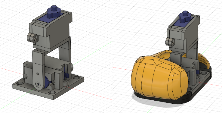
I start with the right leg. The SG92R is fixed to the ankle and the SG90 to the thigh. In addition, the bottom of the leg has removable decorative parts so that it can be freely decorated (Figure 1).
I created decorative parts using the form. I designed them to make it easy to remove them later for maintenance. M2 and M3 screws are used for fixing.

The left leg was made as a symmetrical part using the mirroring function.
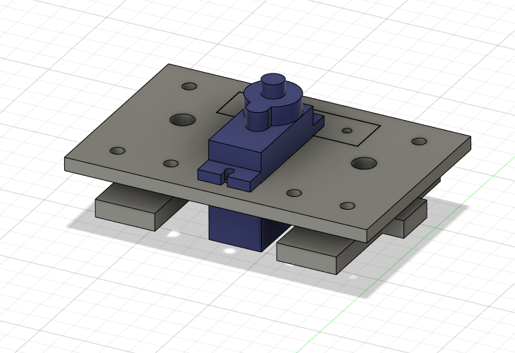
Next is the torso part. Is it the waist rather than the torso? Attach SG90 to turn the head. Some holes for attaching decorative parts are also drilled (Fig. 2).

Finally, the head. The first part is the bottom (Figure 3). The Raspberry Pi Pico will be mounted with a Kitronik servo motor driver board. Two 14500 lithium-ion batteries will be used. The fixing part is a twist-lock system, which can be tightened by turning it because it is tedious to use screws.

The head cover looks like this. The eyes are designed with a form to create a cute design.

Here’s the whole picture (Figure 5)!

So, the prototype design is ready. Will it work well? In the next diary, I will start with printing parts with a 3D printer.
