Create Software! Making Simple Bipedal Robot Part 5
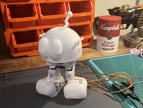
Let’s make software!
Now that the hardware is ready for now, I will start making the software to control the robot. I will use PlatformIO to create the software for the Raspberry Pi Pico that will be mounted on the robot.
Robots need to switch between various postures and poses in different patterns and change their behavior according to the sensor values they receive. It is difficult to achieve all of these with simple conditional branching, etc. It is also difficult to add new poses, so I will consider creating robot software as a “state machine.”
What is State Machine?
You may not be familiar with the term “state machine.” It is also called a Finite State Machine, and refers to a machine that changes its behavior by transitioning from one state to another. This method is effective for robots that are placed in a variety of situations and need to behave differently in each situation. For example, a robot that “walks, sometimes looks around, and after a while goes to sleep” is represented as shown in Figure 1. This representation is called a state transition diagram.
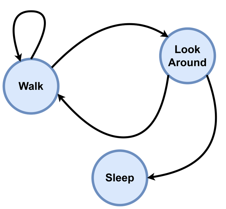
In Figure 1, each circle represents a state. The arrows represent transitions from one state to another. The arrow that leaves a state and returns to itself represents the repetition of that state. In this diagram, the “walk” state is repeated, sometimes transitioning to the “look around” state, and sometimes transitioning from “look around” to “sleep.” This transition can be a specific condition or a probability.
In this way, by preparing all possible situations a robot can take as “states” and connecting the states with transitions, even complex behaviors can be expressed concisely.
This time, I will make it so that it can be implemented in software in the form of this state machine for later use.
State machine implementation!
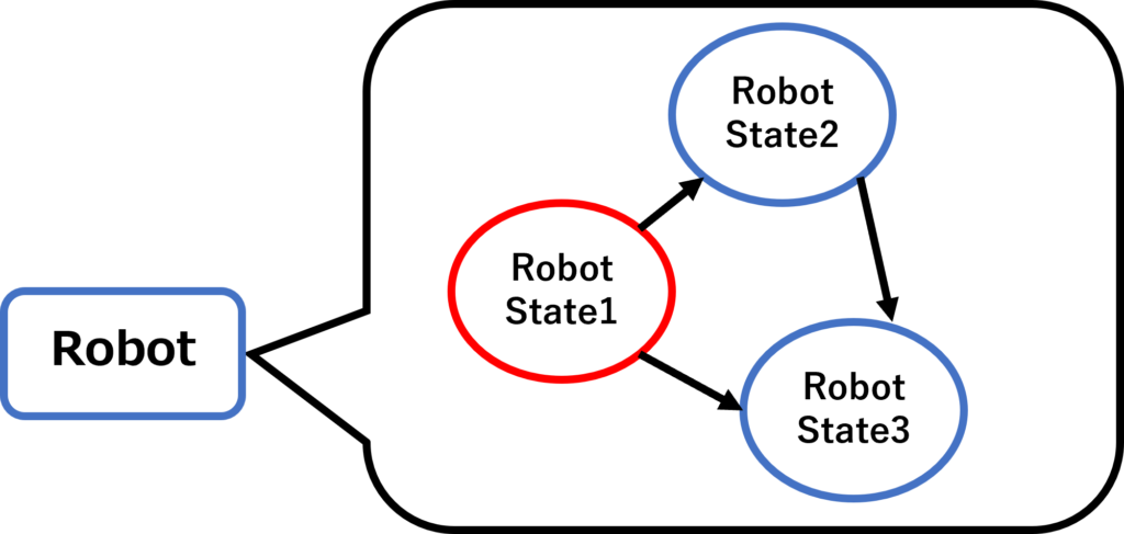
This time I will implement it in C++ using PlatformIO. First, I will create a Robot class. This class will be responsible for the overall management of the robot. Next, I will create a RobotState class.
This is the “state” in the state machine. RobotState also registers another state and allows the robot to transition to that state according to conditions (Figure 2). In reality, there are many more details to implement, but this is the outline of the implementation.
All of these classes are used as base classes and are inherited and implemented by subclasses. In essence, the idea is to prepare only a form as a template and implement it differently for each individual use.
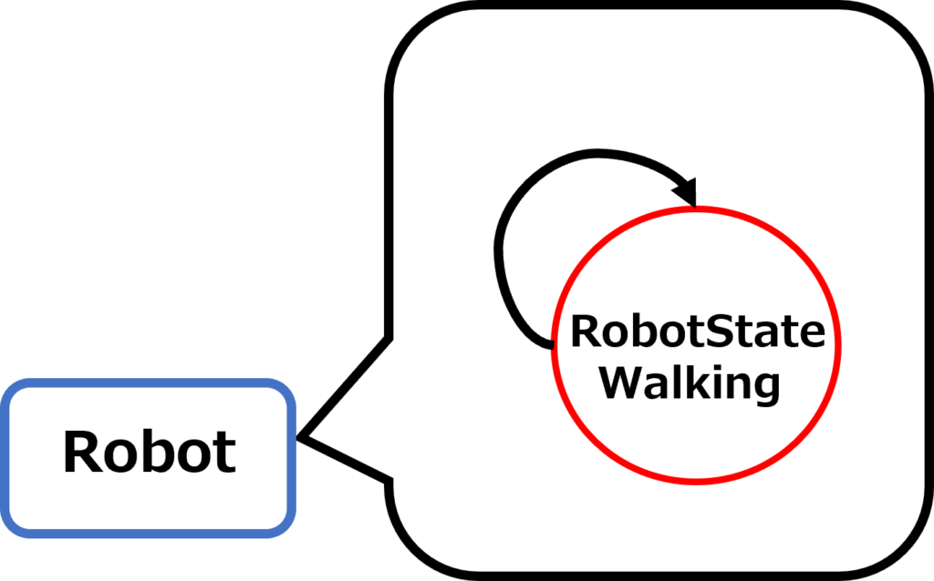
For now, let’s prepare a state that performs one motion and let it run (Figure 3).
Create a state of a head-shaking motion and a state of a walking motion, and run one of each.
Testing the operation
Let’s see it in action! First, here is the head-shaking motion (Video 1)
Next is the walking motion (Video 2).
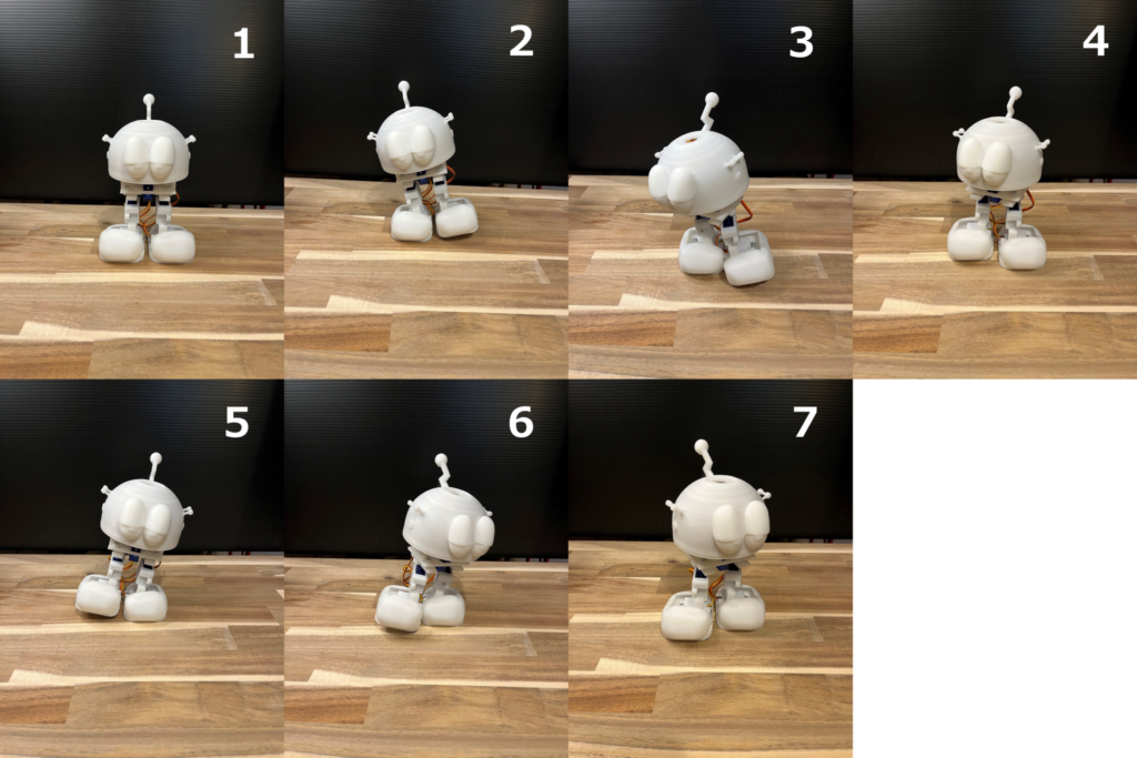
The walking motion consists of repeating six postures. Walking is performed by repeating these six postures in sequence.
As shown in Figure 4, one leg is raised at (2), brought forward at (3), and lowered at (4). Do the same on the other side, (5), (6), and (7). It seems to walk properly!
Incidentally, the SG90 servo motor on board is originally designed to operate at 4.8 V, but it also works well at 3.7 V with a single battery.
What to do about the hunting problem
Now here is a problem. Let’s take a look at Video 3. This is when I did the center of gravity test.
Video 3: Servo motor in the neck part hunting
Can you see that the head occasionally shakes in small increments? This phenomenon of the servomotor shaking in small increments, especially when it is at a standstill, is called “hunting.”
It does not cause serious problems right away, but it can cause the whole body to vibrate, which can have some negative effects in the future, and most importantly, it does not look good.
In the next article, I will create a more complex motion with less hunting.
