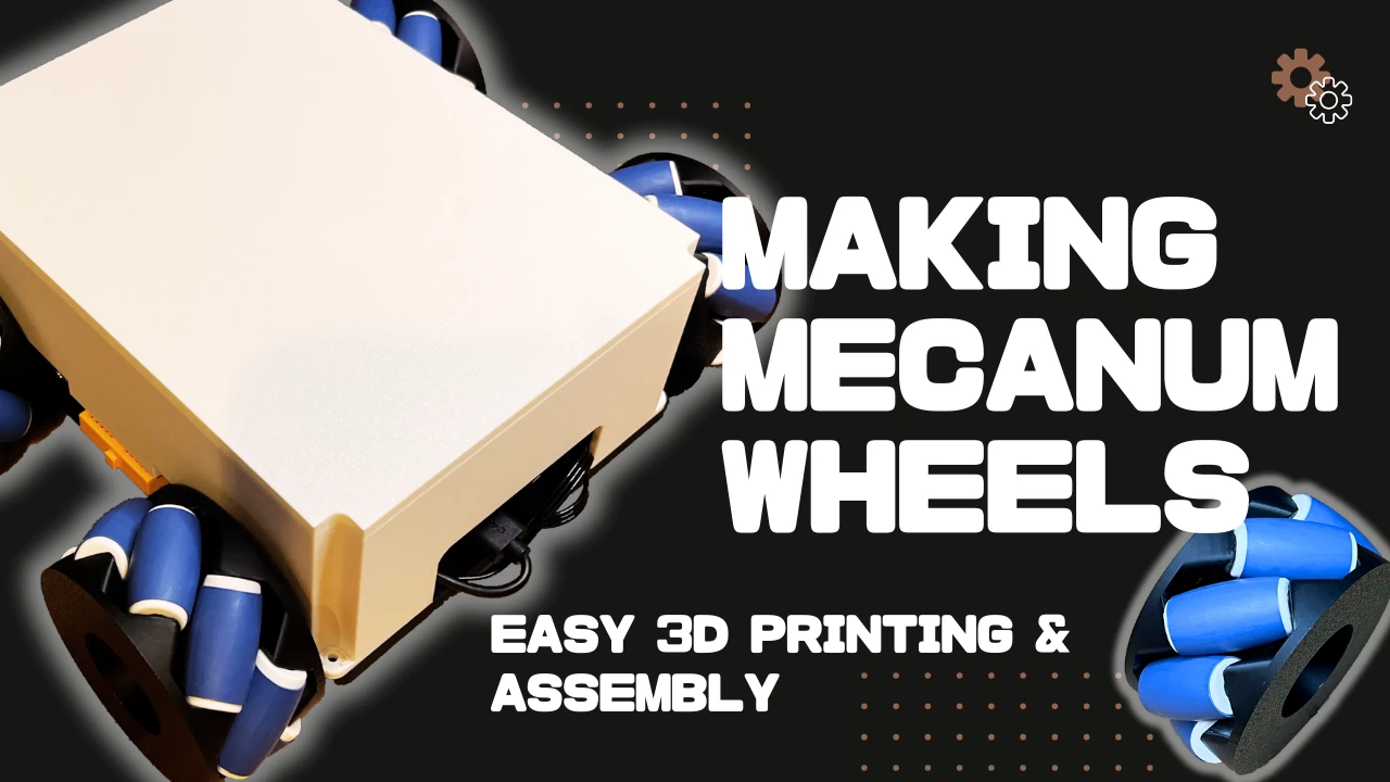
Easy to Print and Assemble Mecanum Wheels!
Toon Robotics is supported by its audience. When you purchase through links on my site, I may earn an affiliate commision.
Summary
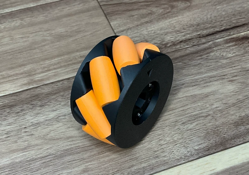
I have created a mecanum wheel you can 3D print and easily assemble to make your own!
The mecanum wheel is mostly 3D printed. It can work with different actuators using adapters.
It is available for sale here. You can print STL files right away. You can also edit design files by using STEP files to create new parts.
This article will explain the assembly process.
Highlights
Here is a highlight of how to make it. Please watch it as well.
Let’s make mecanum wheels!
A mecanum wheel is an omni-directional wheel, which can move in any direction by simply rotating the wheel without a steering mechanism. It has a characteristic shape with rollers mounted at a 45° angle around the wheel.
There are several mecanum wheels available. However, there are various limitations, such as high cost, limited availability, and lack of the right shape for the actuator to be used.
Some people publish 3D printable models, but they have limitations. These limitations include being difficult to create and requiring multiple parts.
So I created a mecanum wheel that can be (1) easily printed with a 3D printer, (2) easily assembled, and (3) easily connected to various actuators!
Preparation
Here is a list of the items required.
- Printed STL files of Easy to Print and Assemble Mecanum Wheel
- M2 screw 25mm or more 3 pcs.
- M2 nut 6 pcs.
Get your screws and nuts from a home improvement store or somewhere similar.
Besides this, you will need a robot car to connect mecanum wheels. For more information on how to use mecanum wheels and robot cars, please refer to this document. You will also find other experimental robot cars in the next article.
tuginokiji
The STL files included in Easy to Print and Assemble Mecanum Wheel are below.
- wheel_top_R.stl
- wheel_top_L.stl
- wheel_bottom_R.stl
- wheel_bottom_L.stl
- sub_roller.stl
- universal_adapter.stl (if necessary)
- universal_shaftless_adapter.stl (if necessary)
- LX-224_adapter.stl (if necessary)
- LX-1501_adapter.stl (if necessary)
- sub_roller_for_TPU.stl (if necessary)
- sub_roller_pillar_for_TPU.stl (if necessary)
The wheel has two main parts: wheel_top and wheel_bottom. We use four sets of mecanum wheels: two with wheel_top_R and wheel_bottom_R, and two with wheel_top_L and wheel_bottom_L.
To make the roller, we use sub_rolle.stl. Depending on the floor surface, we may need additional grips, which we will discuss later.
TPU material can also provide grip, so we can use sub_roller_for_TPU.stl and sub_roller_pillar_for_TPU.stl to make the TPU roller.
To attach the axle, use the item called (type name)_adapter.stl (referred to as “adapter”). This set includes universal_adapter.stl and universal_shaftless_adapter.stl. You can drill holes in the mounting points yourself. I also offer LX-224_adapter.stl and LX-1501_adapter.stl specifically for HiWonder’s LX-224 and LX-1501 servo motors. I provide design data in a STEP file, allowing you to create your own adapter. This means you can customize the adapters to fit your specific needs.
How to make mecanum wheels
To begin, let’s print out all the components. Figure 1 shows a picture of all the printed components.
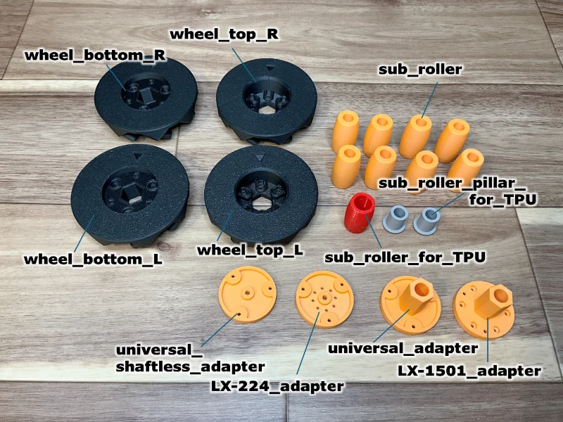
The items were printed using Bambu lab X1 Carbon in PLA. Only the sub_roller_for_TPU was printed in TPU, and it is optional. Different printers and materials can also be used.
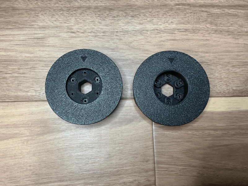
Preparation of wheels
First, prepare the wheel. Create a combination of wheel_bottom_R and wheel_top_R, as well as wheel_bottom_L and wheel_top_L. You will need two sets of each (see Figure 2).
Preparation of rollers
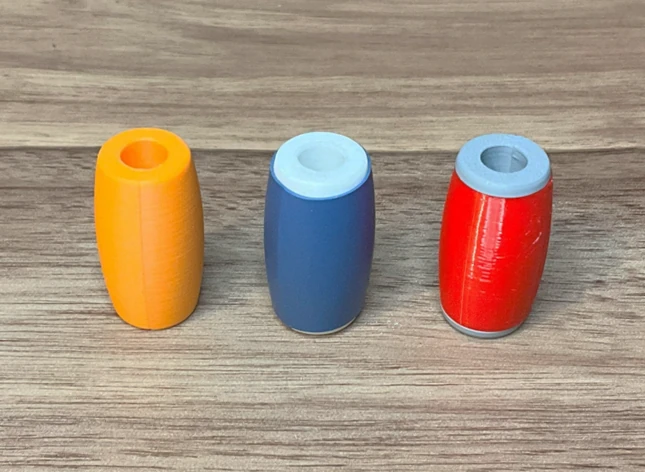
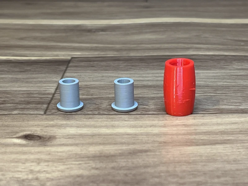
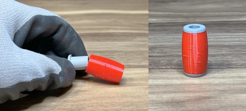
Prepare eight rollers for each mecanum wheel. If the floor has enough friction, use PLA to print sub_roller. If the floor is slippery, process the rollers for more grip or create TPU rollers using TPU roller parts, as explained in “If the roller does not have enough grip” (Figure 3).
The following explanation uses a roller coated with a heat shrink tubing (center of Figure 3), as described in “If the roller does not have enough grip”. However, the assembly procedure is the same for PLA and TPU rollers.
Wheel Assembly
Fit the roller into one side of the wheel part, as shown in Figure 4.
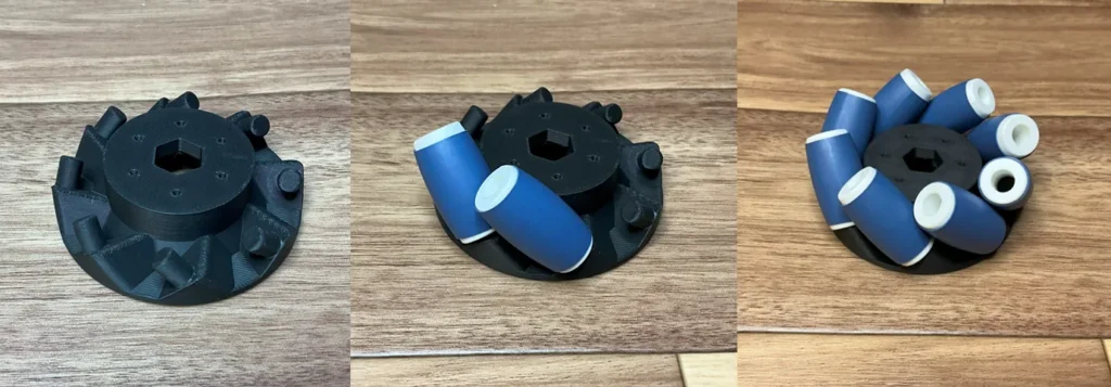
After fitting the eight rollers, combine the other wheel parts (Figure 5). Align the arrows on the outside of the wheel so that they are in the same position (Figure 6).
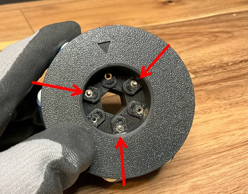
Once firmly fitted, fasten the screws. As shown in Figs. 7 and 8, insert an M2 nut on the wheel_top side and fasten using three M2 screws of 25 mm or larger from the wheel_bottom side.
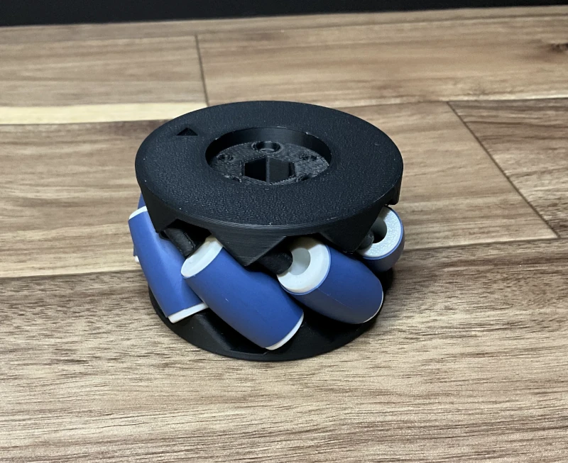
After you fasten all three screws, it should look like Figure 9.
If it is difficult to rotate the roller, lightly sand and adjust the roller.
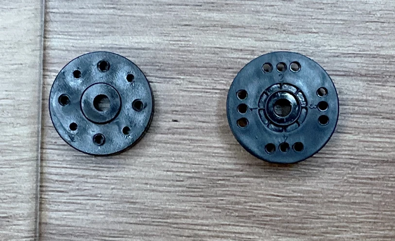
Preparation of adapters
I have prepared four adapters: universal_adapter.stl, universal_shaftless_adapter.stl, LX-224_adapter.stl, and LX-1501_adapter.stl. The LX-224_adapter.stl and LX-1501_adapter.stl are made for using HiWonder’s servo motors LX-224 and LX-1501 in motor mode (continuous rotation servo). This allows for easy attachment of the included servo horn.
The universal_adapter.stl and universal_shaftless_adapter.stl files are designed to connect with the continuous rotation servo or motor by drilling holes or making other modifications. If you can use CAD software, you can create your own adapter with the STEP file provided.
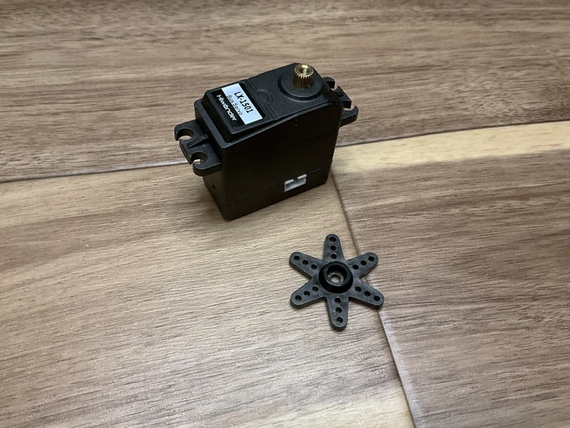
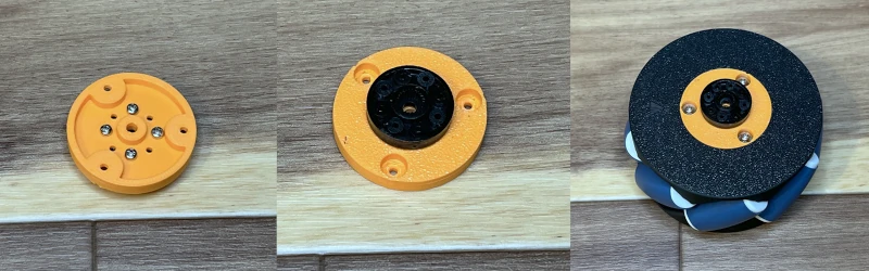
First, I will explain the procedure when using HiWonder’s LX-1501 (Figure 10). The basic flow is the same for other servos, universal_adapter, and universal_shaftless_adapter.
Click here to see how to use Hiwonder’s servo motors in motor mode.

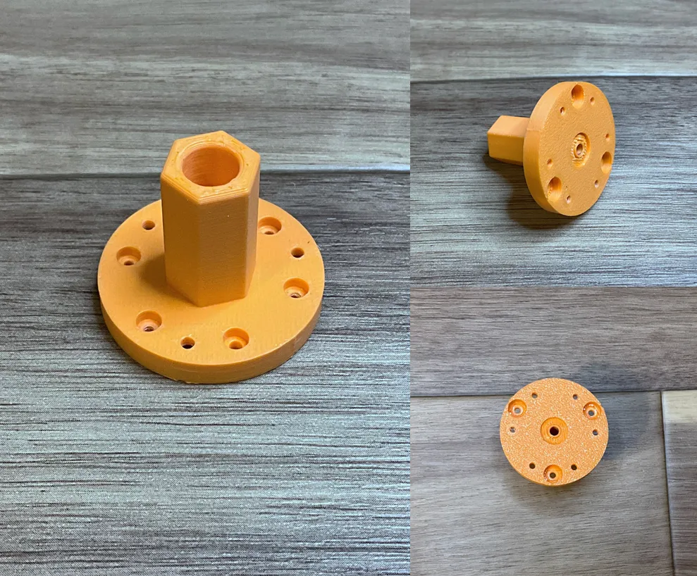
Figure 11 shows the LX-1501_adapter.
Next, attach the servo horn to the adapter by screwing it on (see Figure 12). Once you securely fix it in place, as shown in Figure 13, it’s ready. For this step, I used 8mm M2 screws.
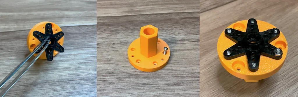
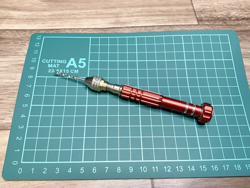
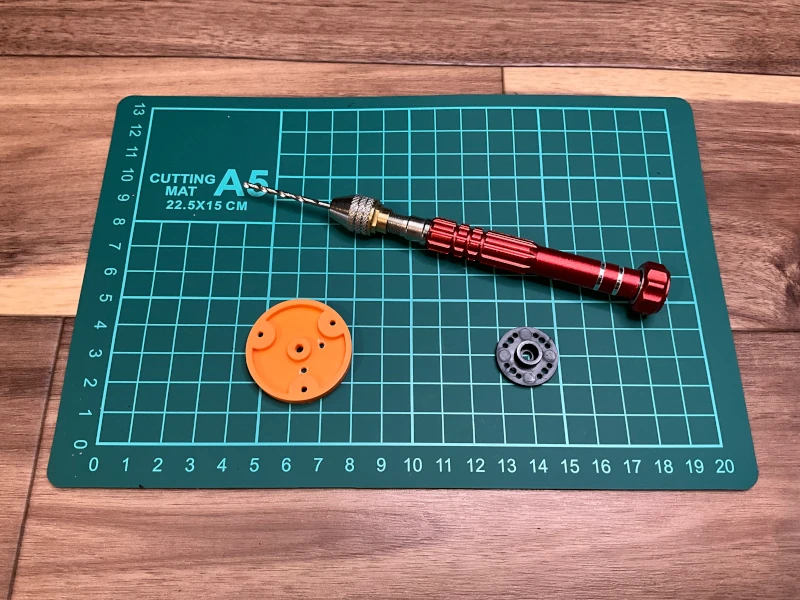
If the screws do not fit into the servo horn holes, you can use a pin vise to widen the holes slightly (Figures 14 and 15).
Mounting the adapter
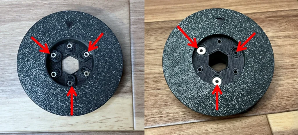
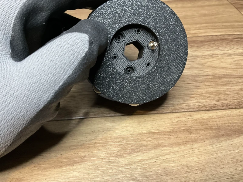
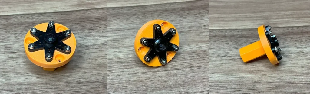
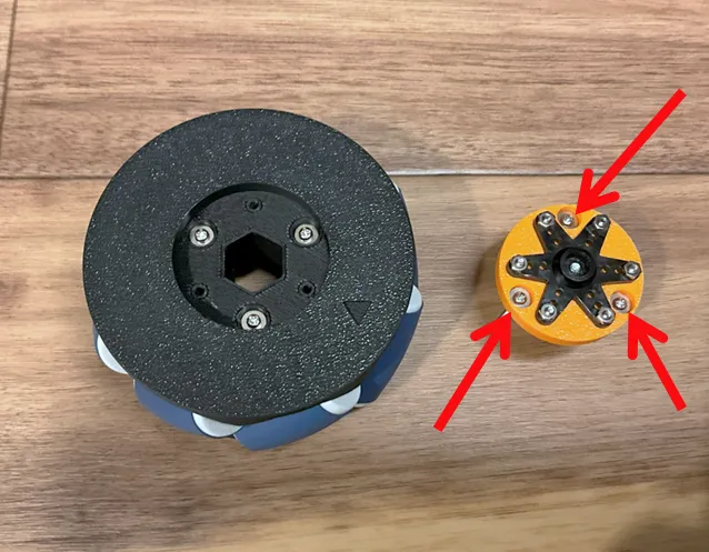
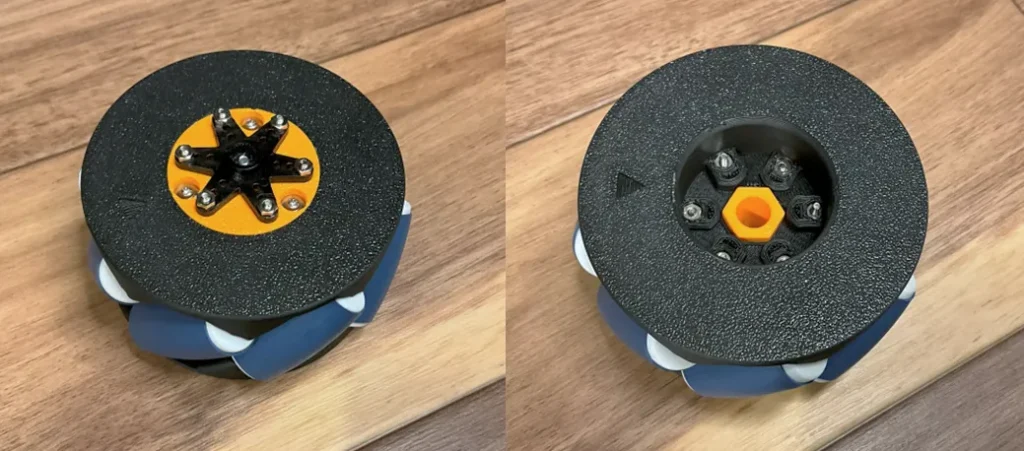
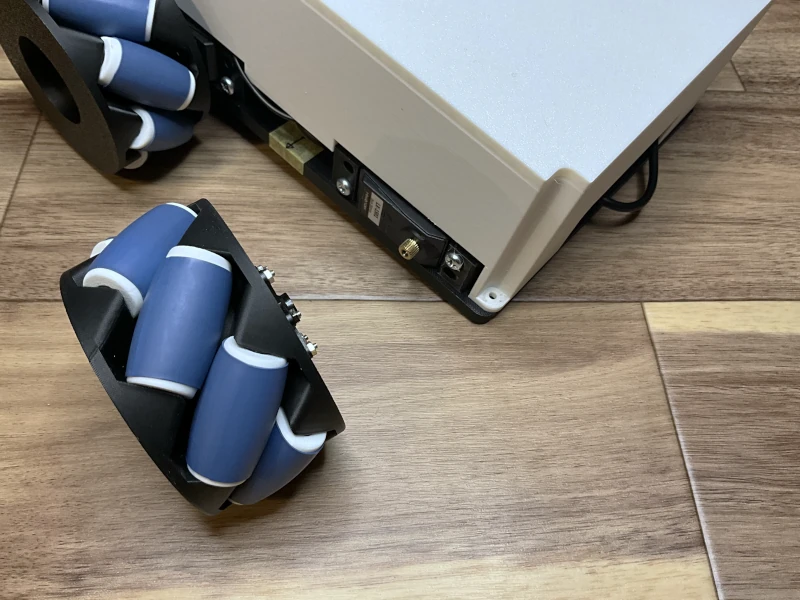
When the adapter is ready, insert a 25 mm M2 screw into the hole showed by the arrow in Figure 16, and further into the remaining hole in the wheel_bottom side of the wheel. Then, fasten the adapter to the wheel by screwing in the nut on the wheel_top side (Figure 17).
Examples of other adapters
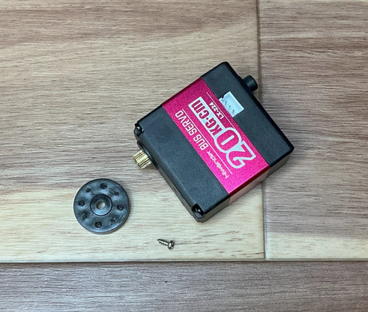
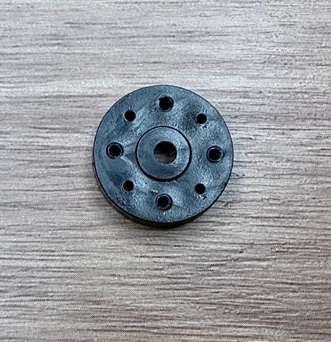
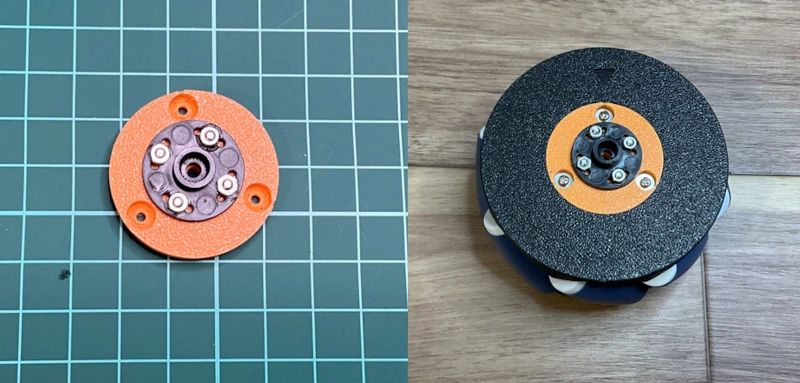
Another adapter, LX-224_adapter for HiWonder’s LX-224 (Figure 18), is also available.
The assembly procedure is similar (Figures 19 and 20). Use the provided screws to secure the servo horns to the adapter.
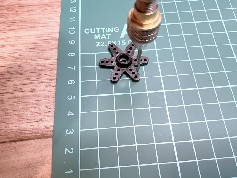
When installing servo horns or axle fixing hubs of different sizes, you can drill holes in the universal_adapter or universal_shaftless_adapter by yourself (Figure 21). The assembly procedure is the same, except for drilling holes in these adapters using a pin vise or similar tool (Figure 22 and 23).
Attachment to axle
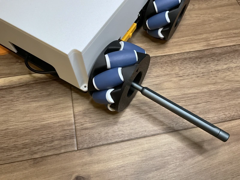
Once this is done, attach the servo horn to the part that will be the axle of the servo motor, etc. (Figure 24).
Servo horns are typically attached to the center of the servo motor’s shaft using screws.
The LX-1501 uses M3 screws (see Figure 25). Attach the actuator based on the type of actuator being used.
If the roller does not have enough grip
Rollers made of PLA material, etc., may not work well on some floor surfaces because of slippage. In such cases, it can be improved by (1) processing the roller or (2) printing with a different material. Let’s start by looking at processing using a heat shrink tubing.
Processing with a heat shrink tubing
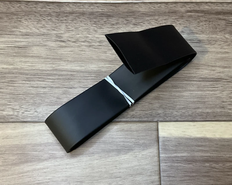
Heat shrink tubing is a tubular material that protects wiring and equipment in electrical circuits. It shrinks when heated and adheres closely to the object.
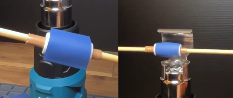
The sub_roller uses heat shrink tubing with a diameter of 18 mm (Figure 26). Heating can shrink this tubing, using a heat gun or a similar device (Figure 27).
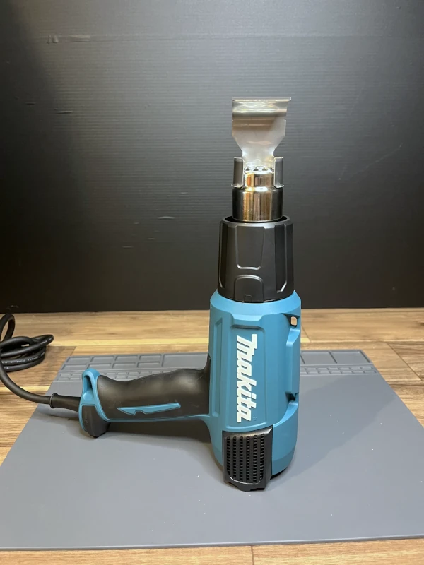
The videos show how to use a heat gun with heat shrink tubing. Following that step, apply heat shrink tubing to the rollers.
Insert the roller into the heat shrink tubing and heat it (Figure 28). Avoid overheating the roller to prevent deformation, finish quickly. When the tubing fits tightly, the process is done, improving roller grip. Once all pieces are ready, assemble them according to Figure 4 in “Wheel Assembly”.
Making TPU rollers
It is also effective to change the material. One of the most effective materials for obtaining a grip is TPU.
To create a TPU roller, use sub_roller_for_TPU and sub_roller_pillar_for_TPU. sub_roller_for_TPU should be made of TPU and sub_roller_pillar_for_TPU should be made of PLA, etc. Print two per roller (Figure 29).
Once printed, insert sub_roller_pillar_for_TPU from both sides of sub_roller_for_TPU (Figure 30).
After preparing the pieces, assemble them according to Figure 4 in the “Wheel Assembly” section.
Usage and roller grip verification
I have experimented and verified that the performance is
TPU ≈ Heat shrink tubing processed PLA > PLA
If the floor surface has high friction, PLA alone will work well. It’s advisable to use different rollers based on the situation. The performance of the TPU roller and the PLA roller processed with heat shrink tubing were almost the same. Choose the one that is easier to make in your own environment.
The following article provides more detailed information:
For the latest status, check here.