How to convert a Hiwonder servo to a continuous rotation servo

Toon Robotics is supported by its audience. When you purchase through links on my site, I may earn an affiliate commision.
Summary
Continuous rotation servos are handy, but surprisingly few are available. This guide shows how to convert Hiwonder servos to continuous rotation servos.
If you have an Arduino or other board with serial communication (UART), you can easily convert it to continuous rotation.
What is Continuous Rotation Servo?
Unlike standard servomotors, which control angles, continuous rotation servos only control rotational direction and speed. This lack of angle limits makes them ideal for continuously rotating applications, such as wheels.
Compared with conventional DC motors, the servomotors are easier to handle because they require no additional circuits or mechanisms to manage and operate.
Thus, a continuous rotation servo is very useful, but there are few servo motors offered as continuous rotation servos.
There is a way to modify a normal servo and make it rotate continuously, but it requires a lot of time and skill.
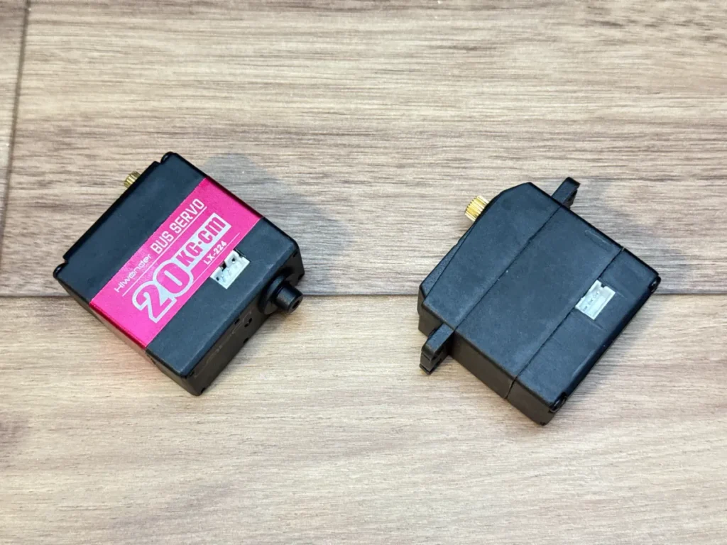
Hiwonder servo motor that can be used as a continuous rotation servo
Some Hiwonder servos easily convert to continuous rotation.
There are two types of Hiwonder servo motors: PWM servos and serial bus servos. The serial bus servo motor is the one we will focus on this time.
For example, the following products fall under this category.
Hiwonder LX-1501: https://www.hiwonder.com/collections/bus-servo/products/lx-1501
Hiwonder LX-224: https://www.hiwonder.com/collections/bus-servo/products/lx-224
Other serial bus servos from Hiwonder seem to work as well, so I think the following products may also apply (not tested).
Hiwonder LX-225: https://www.hiwonder.com/products/lx-225
Hiwonder HTS-35H: https://www.hiwonder.com/collections/bus-servo/products/hts-35h
You can easily convert these serial bus servos to continuous rotation by setting them up.
You can control servomotors easily by The Hiwonder Serial Bus Servo Controller and its software. However, the software can’t continuously rotate multiple servos (as of 2025/6/17, Bus Servo Control V3.0). This is a problem when using multiple servos, such as for a wheel.
Hiwonder Serial Bus Servo Controller: https://www.hiwonder.com/products/serial-bus-servo-controller
However, you can easily control Hiwonder serial bus servo motors without using such dedicated controllers and software. It is also possible to make them rotate continuously. Let’s take a look at how to do this!
Circuit configuration
Here, we assume an Arduino Uno R4 Minima as the control board. You can also use other boards that support serial communication (UART). For the servo motors, we assume the LX-1501, but other servomotors can be used as well. You should connect, as shown in Figure 2.
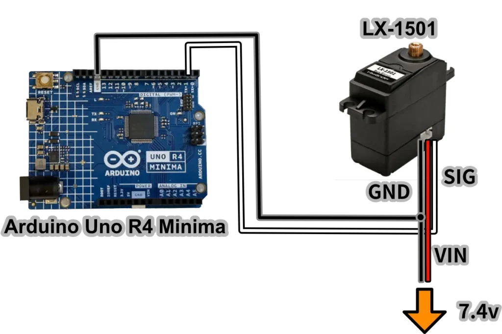
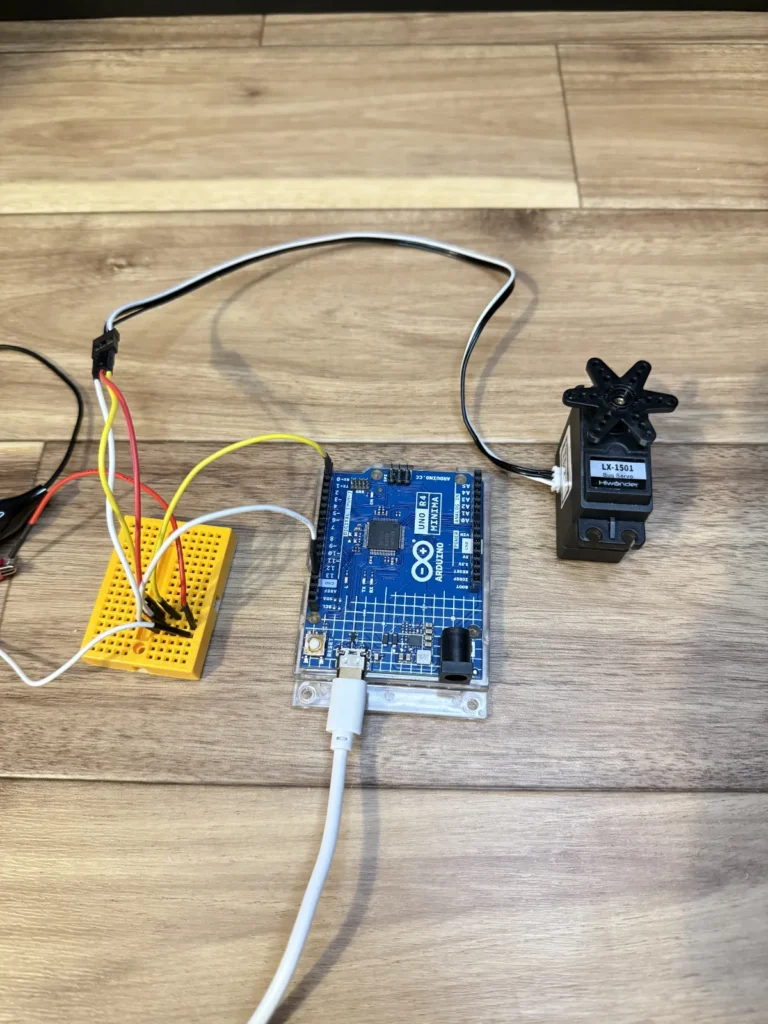
Connect a 7.4v power supply to VIN on the LX-1501.
I used two 3.7V 14500 lithium-ion batteries in series and also connected a separate power supply to the Arduino.
Power the Arduino with a portable battery pack or similar. Connect the LX-1501’s GND to both the Arduino’s and the power supply’s GND. Connect the LX-1501’s SIG (signal line) to the TX pin for serial communication; for an Arduino Uno R4 Minima, use digital pin 1.
JST PH connectors are used for connection to the servo motor. Use the supplied cable, or the connector shown below to connect.
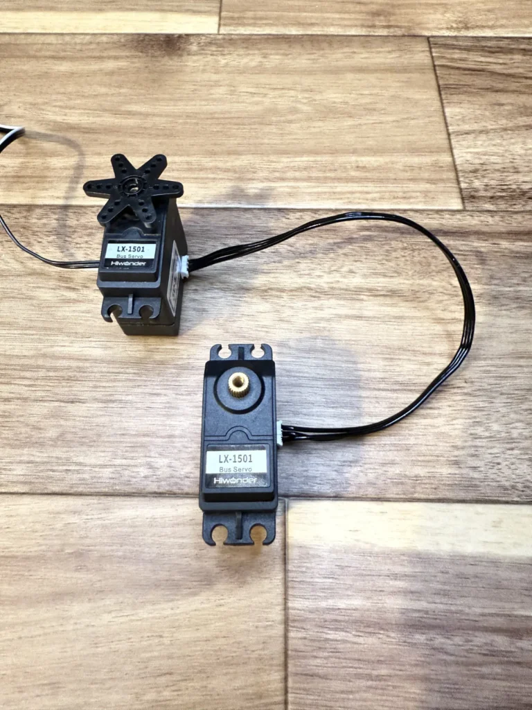
Also, servo motors such as LX-1501 and LX-224 can be daisy-chained, so if you want to connect multiple servo motors, you can directly connect more servo motors from those already connected to a control board such as Arduino (Figure 4).
Thereafter, the actual process of use will be as follows.
- 1) Change and assignment of ID numbers
- 2) Operate servo motors
1) Change and assignment of ID numbers
Each Hiwonder servo has an ID. This mechanism allows you to give different movement instructions to each specific servo. By default, the servomotor has ID number 1, so change this if needed.
2) Operate servo motors
Next, command the servomotors. You can control any servo by its ID number, rotating it in either direction. We’ll focus on continuous rotation here, but this method also works with standard angle control.
Programming
Let’s take a look at the program. We will start by changing the ID number.
Prepare an Arduino sketch.
Use “include.h” and “SerialServo.h” from the official Hiwonder source code. Add these two files to the same directory as the prepared sketch. (You can find the page at https://www.hiwonder.com/→Tutorials→Servo&Servo Controller→Hiwonder Serial Bus Servo→Download All→LX-1501 Serial Bus Servo→1. Tutorial→2. Bus Servo Secondary Development→1. Arduino Development(as of 2025/06/17))
include.h and SerialServo.h define constants and functions, respectively.
Prepare a program to change this ID. The following is the program (Arduino sketch). Connect only one servo.
#include "include.h"
#include "SerialServo.h"

void setup() {
  Serial1.begin(115200);
  delay(1000);

  int oldID = 1;
  int newID = 2;

  LobotSerialServoSetID(Serial1, oldID, newID);
}

void loop() {

}
oldID is the current ID, and newID is the ID to be changed. The function used to change the ID is LobotSerialServoSetID.
Running this program with the servomotor and Arduino connected will change the ID. Change the numbers in the newID section if necessary.
Once this is done, make another sketch. Let’s move the servo motor.
#include "include.h"
#include "SerialServo.h"

int speed = 700;
int wait = 3000;
int ServoID = 2;

void setup() {

  Serial1.begin(115200);
  delay(1000);

}

void loop() {

  LobotSerialServoSetMode(Serial1, ServoID, 1, speed);
  delay(wait);

  LobotSerialServoSetMode(Serial1, ServoID, 1, 0);///stop rotation
  delay(1000);

  LobotSerialServoSetMode(Serial1, ServoID, 1, -speed);
  delay(wait);

  LobotSerialServoSetMode(Serial1, ServoID, 1, 0);///stop rotation
  delay(1000);

}
For normal angle control, use the LobotSerialServoMove function, but for continuous rotation servo, use LobotSerialServoSetMode.
In LobotSerialServoSetMode, the first argument is the HardwareSerial of the Arduino, and the second argument is the servo ID to control.
The third argument specifies the mode. 0 specifies angle control, and 1 specifies motor mode. Here, we want to use it as a continuous rotation servo, so we set it to 1. The fourth argument is the rotation speed. This value can range from -1000 to 1000, with negative values resulting in reverse rotation. In the above sample program, the motor rotates in the order of forward rotation, stop, reverse rotation, and stop.
You can individually control each servo by assigning it an ID number, making them suitable for robot wheels and similar applications. They also work with angle control, letting you daisy-chain all wheels and standard angle servos for independent movement.
For the latest status, check here.