Assemble 3D printed parts! Making Simple Bipedal Robot Part 4

Assembling the Robot
So far I have finished 3D printing all the parts. Now I will start assembling the printed parts.
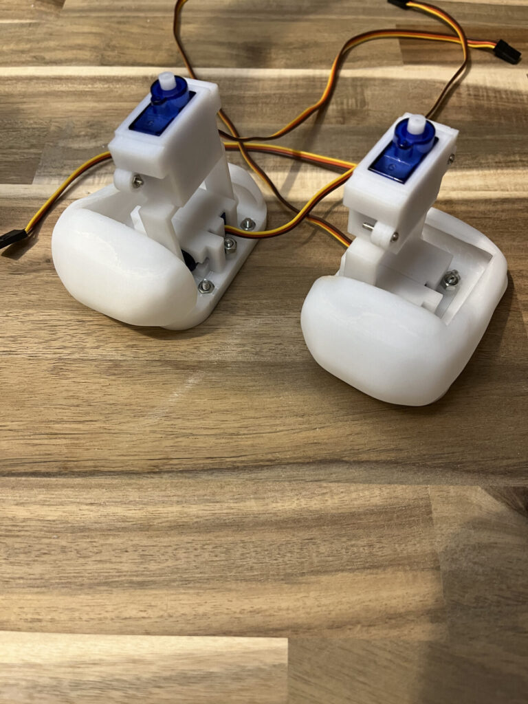
First, the legs. The legs are the most complex part and are equipped with one SG90 and one SG92R servo motor, for a total of four servo motors in both legs (Figure 1). One for the roll at the ankle and the other for the yaw motion at the thigh. The SG92R is placed at the ankle, where more power is expected to be required.
The terms “roll” and “yaw” are used to refer to Euler angles, which consist of roll, pitch, and yaw.
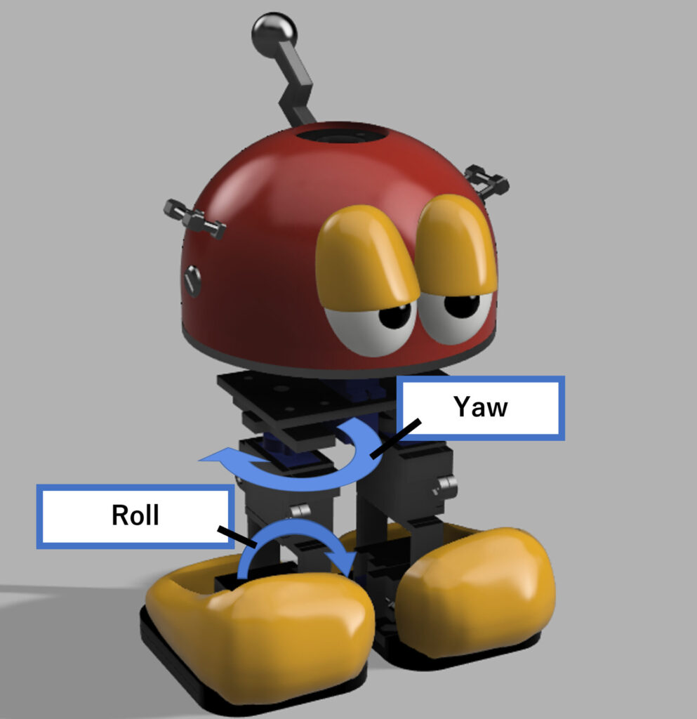
In other words, roughly speaking, roll is the movement of rotation to the left or right with respect to the front of the body, pitch is the movement of rotation up or down, and yaw is the movement of rotation in the horizontal direction. The robot to be created this time consists only of roll and yaw (Figure 2).
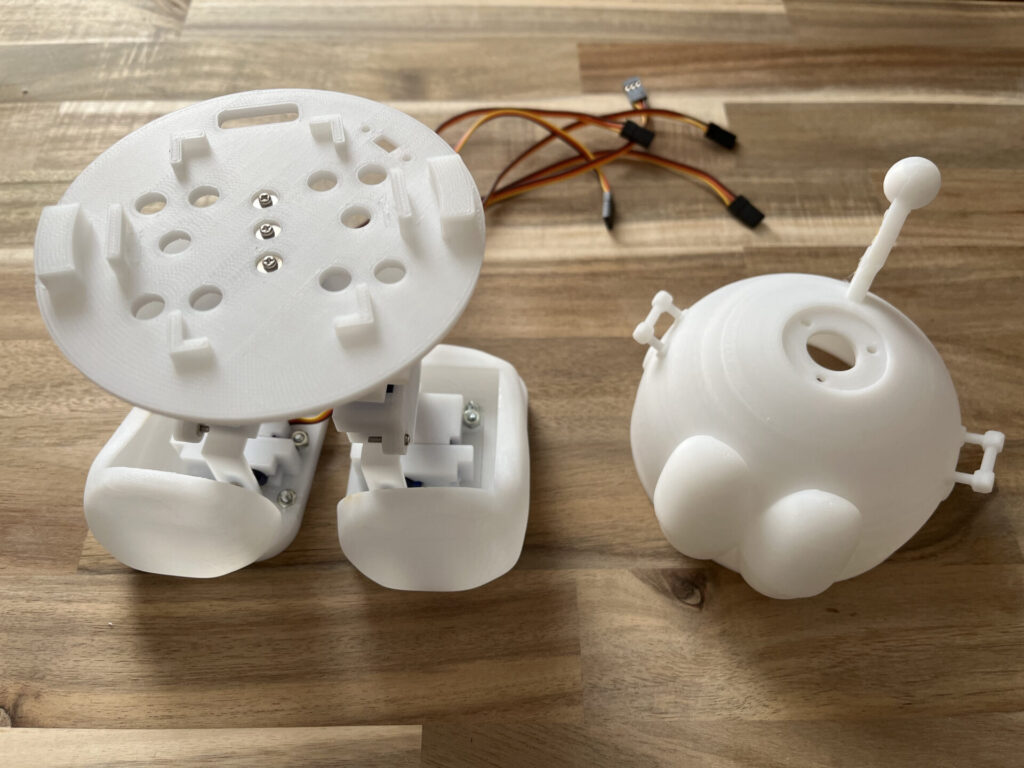
When I installed the SG90 and SG92R, the dimensions were perfect. In this case, I designed the SG90/92R with about 0.3mm more margin than the actual SG90/92R. If this amount of space is not left, the parts will be too tight and it will be difficult to insert the parts, or they may not fit at all. After assembly, the product is shown in Figure 3.
Next is the waist. The shape is a little too complicated, making it difficult to peel off the support material and time-consuming to assemble. A servo motor for turning the head is also mounted (Figure 4).
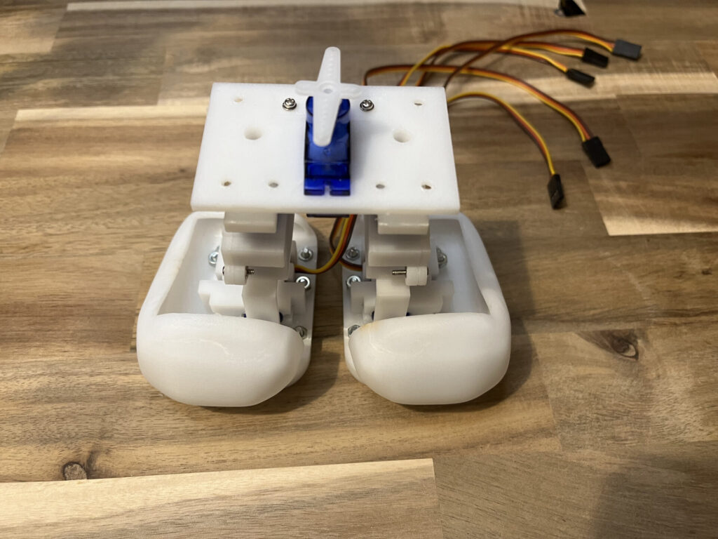
Then place the base of the head part on top of it. (Figure 5)
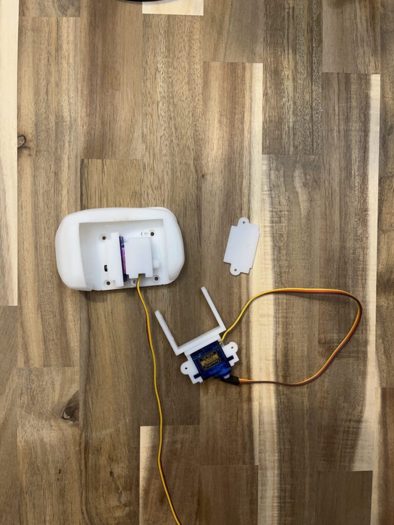
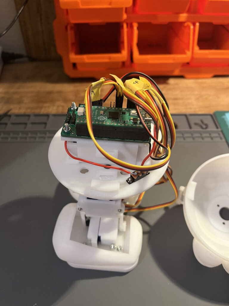
In the center, place the battery box and Raspberry Pi Pico and wire the servo motor cords.
A power switch is also attached. (Figure 6)
Once I’ve made it this far, all you need to do is put the head cover on,
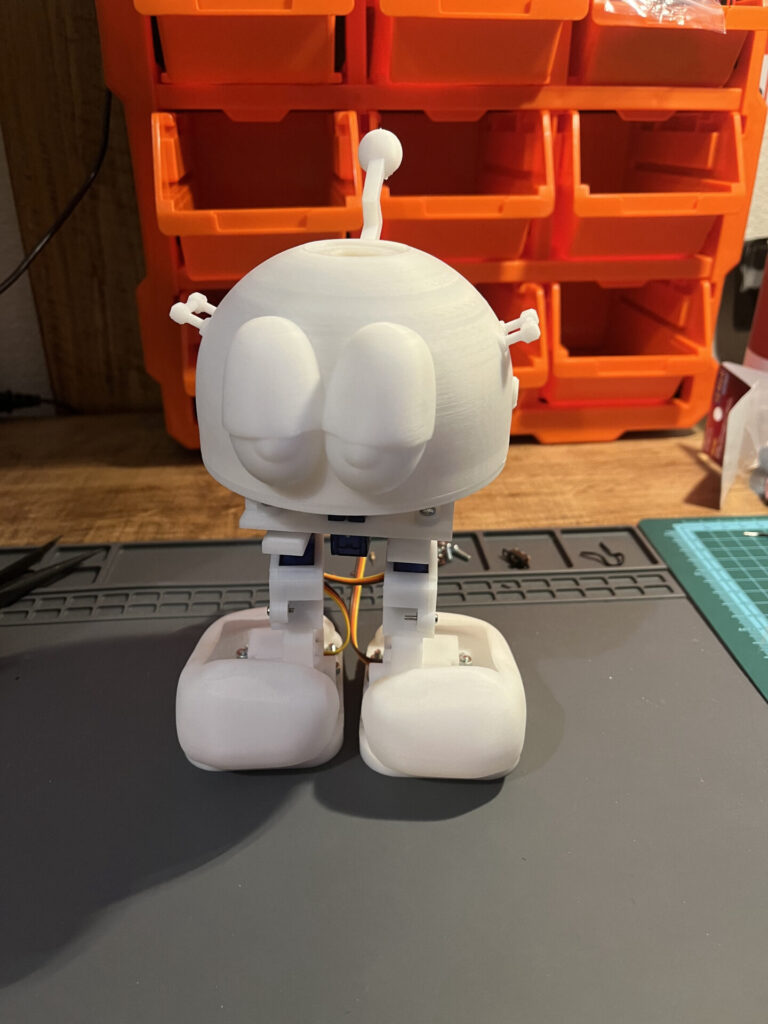
Assembly complete! (Fig. 7)
The screw lock mechanism to secure the head went surprisingly well.
It is still exciting to see the whole thing assembled. The size is also cuter than I thought it would be.
Now that we’ve reached this point, it’s time to test the operation. Next time, I will let it walk!