Making a Simple Bipedal Robot Part 3
Printing with a 3D printer!
Now I will print the robot parts created in CAD with a 3D printer.
The flow of printing data created by CAD with a 3D printer is as follows.
- Designing parts on CAD
- Output as STL files
- Printing setup with utility software for 3D printers
- Printing with a 3D printer
The first part design was done in the previous post. Next, I will output these in the STL file format.
The STL file is a format widely used in 3D printers and was created by 3D Systems in 1987 as part of its stereolithography 3D printer technology, which is one type of 3D printer. It is commonly believed that it was named after Stereolithography, but there are various theories, such as the acronym of Standard Triangle Language.
Once the STL files for each part have been prepared, place them using utility software for 3D printers, and set various parameters for printing.
When finished these processes, all that is left to do is to print it out on a 3D printer.
Convert Fusion 360 data to STL files
The design data for this project was created in Fusion 360, and Fusion 360 can output the data as STL files without modification.
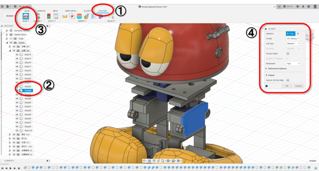
As shown in Figure 1, the following procedure can be used to output as an STL file.
- Open “UTILITIES” tab
- Select the object you want to convert to STL
- Choose “MAKE”
- Make the necessary settings and press “OK.”
Convert to data for 3D printer
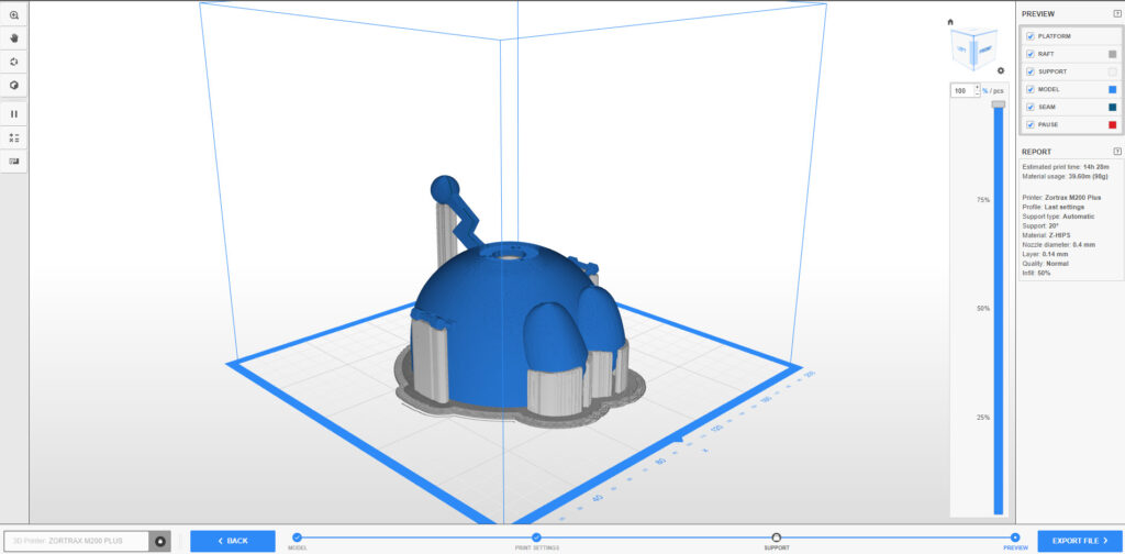
Once the STL files are ready, the next step is to create data for 3D printer printing using utility software for 3D printers (commonly known as “slicer“).
Since I am using Zortrax M200 Plus, I use Z-SUITE provided by Zortrax (Figure 2). Z-SUITE automatically creates the supports for the hollow part based on the given model data and automatically creates the behavior of the 3D printer for the actual printing. In the case of Z-SUITE, the output is a file with the extension zcodex2. All that is left is to send this to the 3D printer and print it.
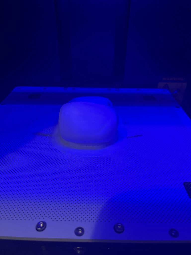
Start printing
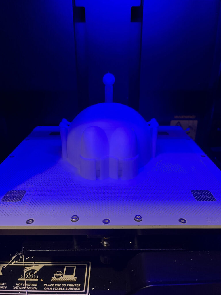
Then, the printing goes on and on! Printing is done by sticking to the central plate, which is then pulled off with a tool called a scraper (Figure 4) after printing is complete.
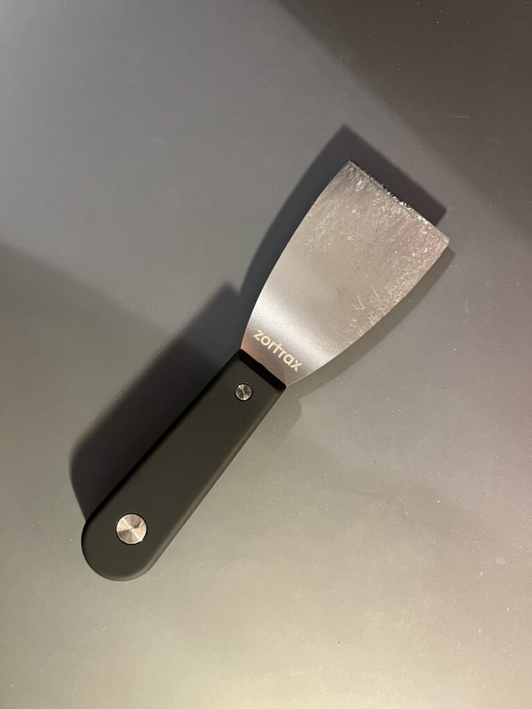
Without it, it is difficult to pull the printed material off the plate.
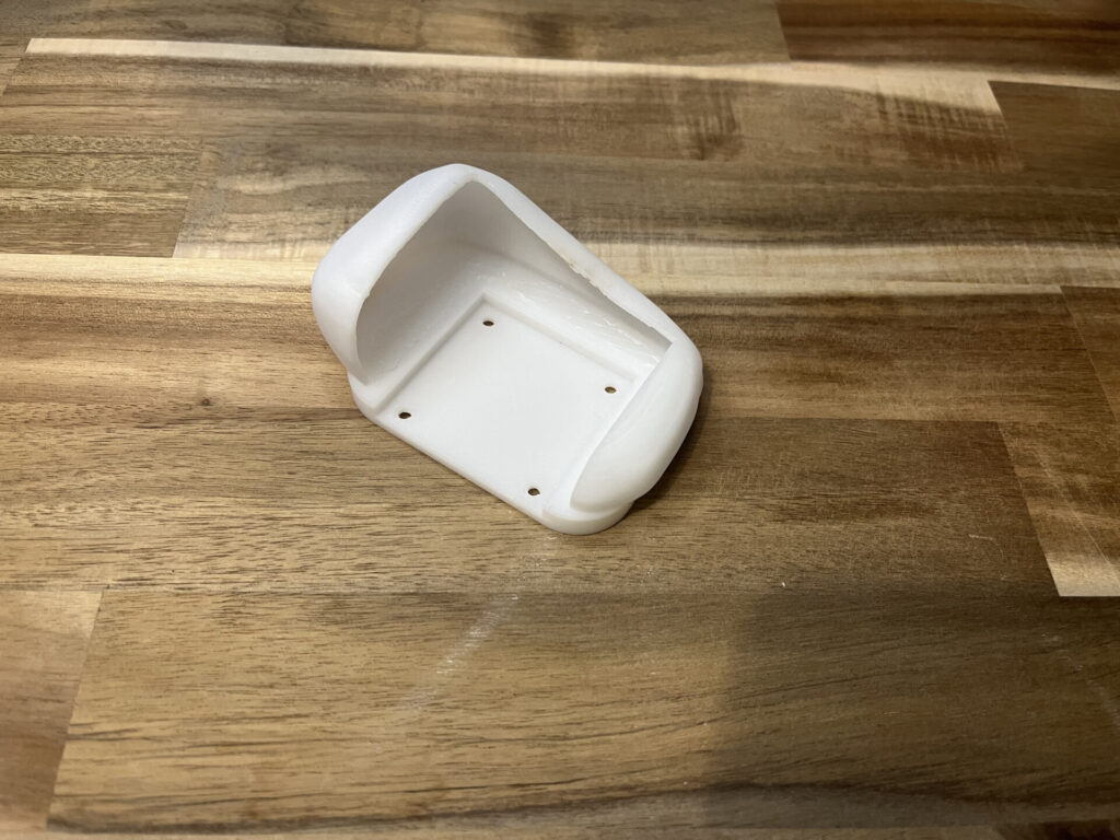
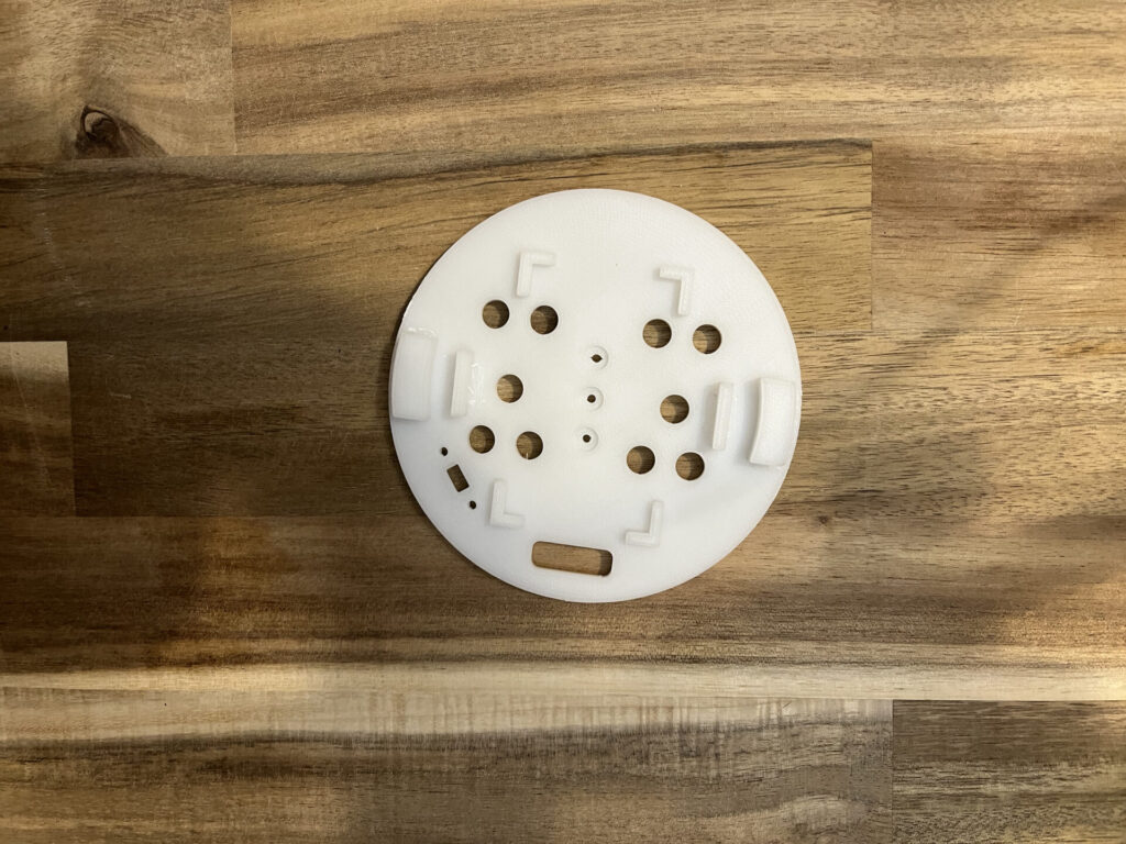
Use a scraper to pull it off the plate, and then cleanly peel off the support and raft, the parts to be printed as a base for the modeling object. Once this is done, the part is completed as shown in Figure 5.
After printing some, check if the dimensions are correct.
If there are no problems, print more and more.
Printing time increases with more complex modeling, more support parts, and larger sizes. The head cover part was quite time-consuming, taking about 14 hours. (Figure 9)

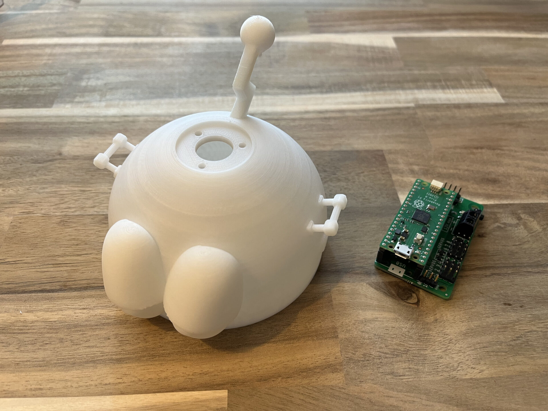
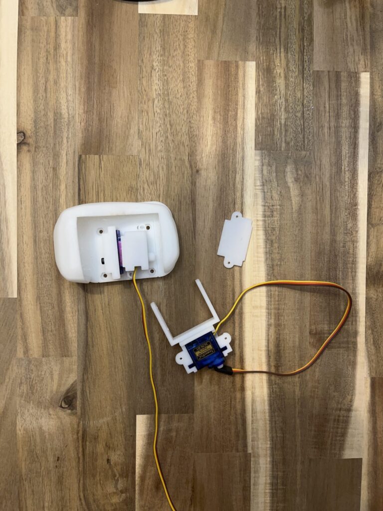
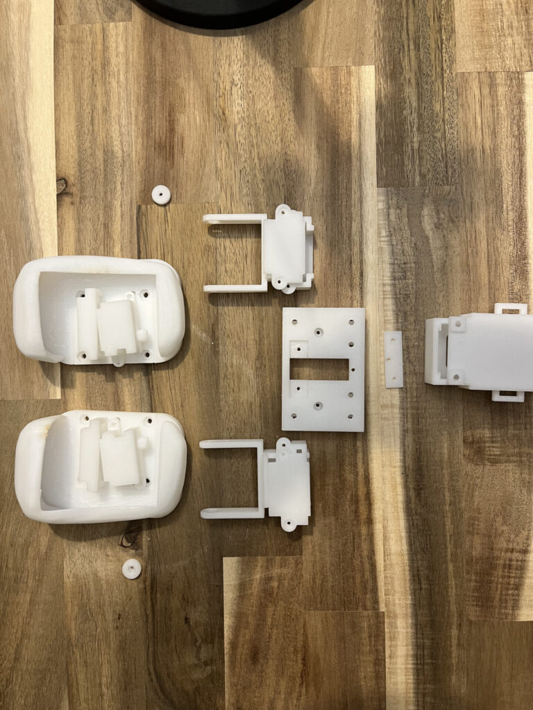
Now, I have finished printing all the parts for the prototype. Next time, I’ll start the assembly process!