Assembling Ver. 2. Building a Simple Bipedal Robot Part 8

Toon Robotics is supported by its audience. When you purchase through links on my site, I may earn an affiliate commision.
Previous Development
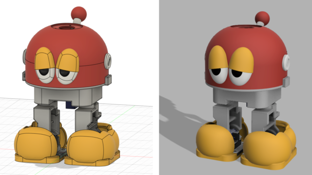
Previously, I developed and printed Ver. 2 with an improved robot body.
Assembly
Now, let’s assemble it.
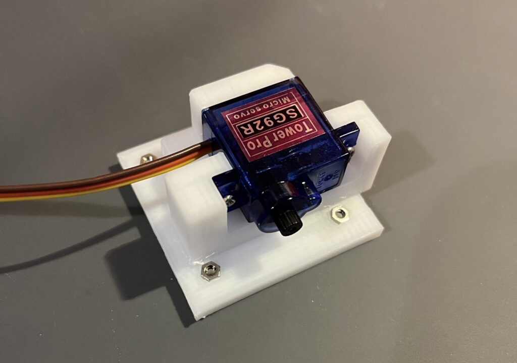
Let’s start with the ankles. Attach the servo motors. It is easier to assemble than before. (Figure 1)
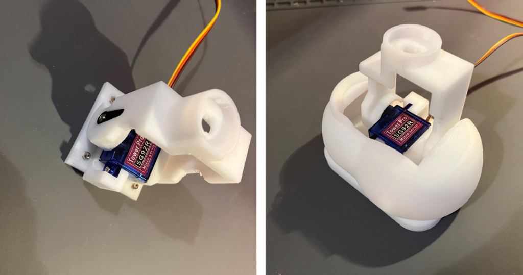
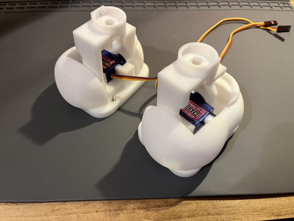
Continue to assemble the legs. These parts are now much easier to assemble. The servo motors are now firmly attached for improved stability. (Figure 2, 3)
Next is the body part. The rotating part of the head has been significantly revised and redesigned to be more compact, easier to assemble, and more stable. (Figure 4)
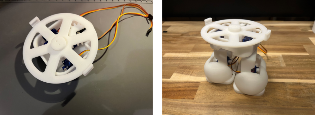
The circuits inside have also been consolidated more efficiently than before. (Figure 5)
The switch is mounted on the head cover side because the mounting position differs from before.
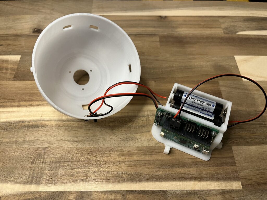
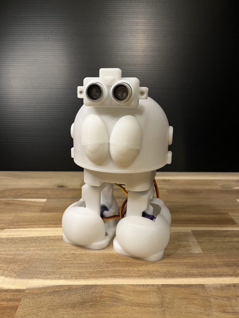
Figure 6 shows the final assembly! The twist-lock mechanism of the head cover is now much easier to use.
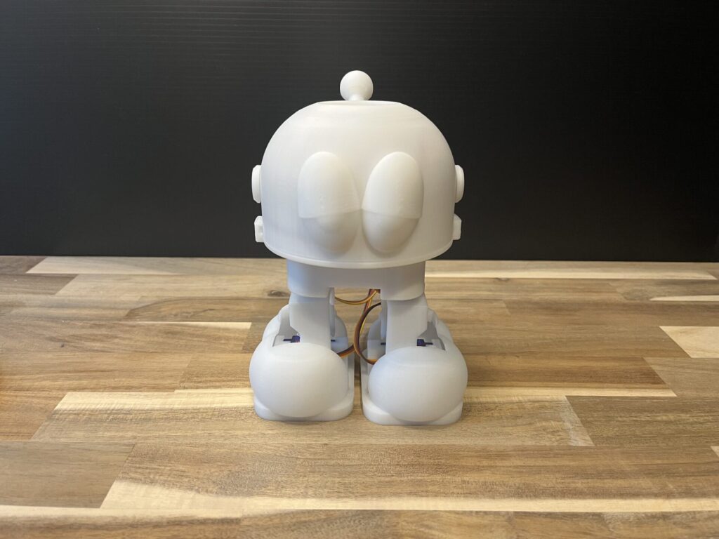
The overall design is cleaner and more stable than the previous one. (Figure 7)
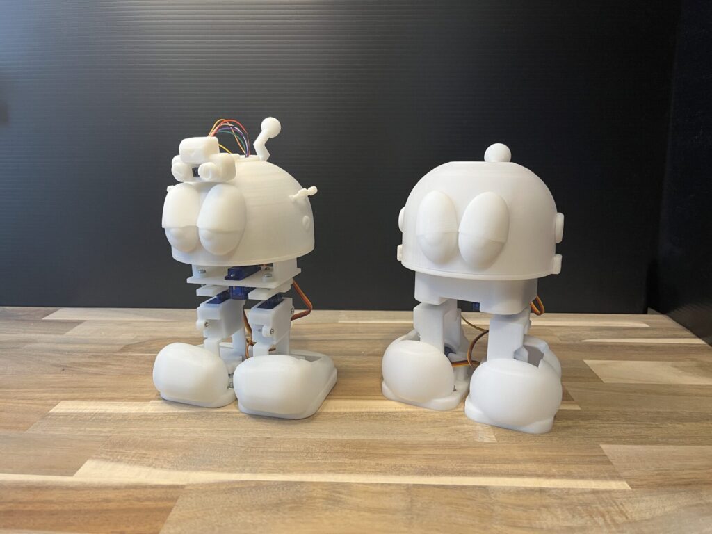
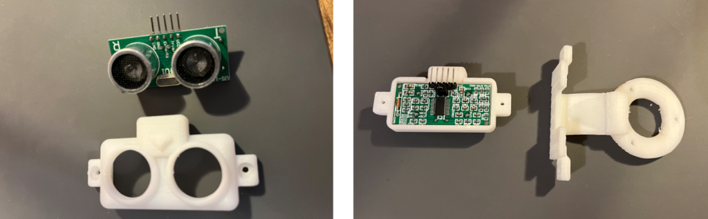
In addition, a goggle-type sensor using the US-100 ultrasonic distance sensor is assembled and installed. (Figure 8, 9)
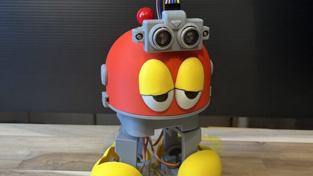
Here is what actually works!
For further upgrading
Now that I have completed the approximate design of Ver.2, I have confirmed its operation. Since I found some parts that still need to be corrected in this implementation, I will make a version with those parts fixed in the future. Next, I will actually do some color printing.
Next
For the latest status, check here.