Version Up! Building a Simple Bipedal Robot Part 7

Toon Robotics is supported by its audience. When you purchase through links on my site, I may earn an affiliate commision.
Previous Development
Previously, I have eliminated to some extent the “jittering” that causes the robot’s servo motors to vibrate, and I have also improved on the power supply.
I was going to build out the sensor mounting and movements…
Now that the overall robot body was completed, I was going to start building the robot’s movements and installing sensors. However, after making the robot up to this point, I began to find various parts of the robot body that I wanted to fix.
So I was working on installing a distance measurement sensor and creating motion…
I’m too concerned about what needs to be improved on the robot’s body.
Therefore, I decided to improve the body of the robot first and foremost.
Then to version 2…
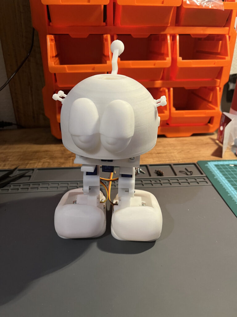
First of all, if the previous robot was version 1, this version 1 looked like this (Figure 1)
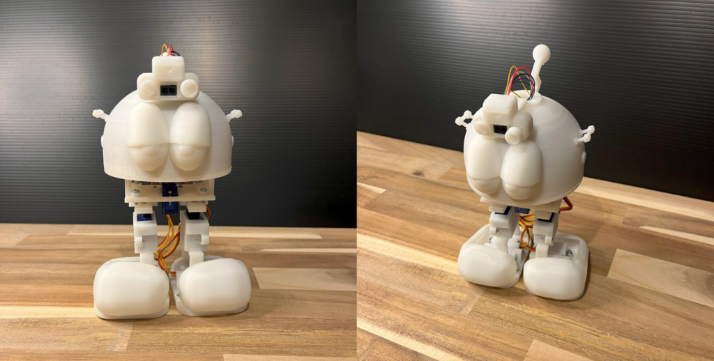
It was equipped with an optical distance sensor, as shown in Figure 2.
GP2Y0E03 is available for sale, for example, on
eBay: https://ebay.us/rNxGVv
AliExpress: https://s.click.aliexpress.com/e/_oBx5ros
The problems with Ver. 1 so far were as follows
- Large rattling at each movement point, especially the head
- Small and fragile decorations
- Insufficient fixation of internal parts
- Some parts are difficult to print and not strong enough
- Difficult to assemble
- Difficult to remove the head
Let’s look at each one of them.
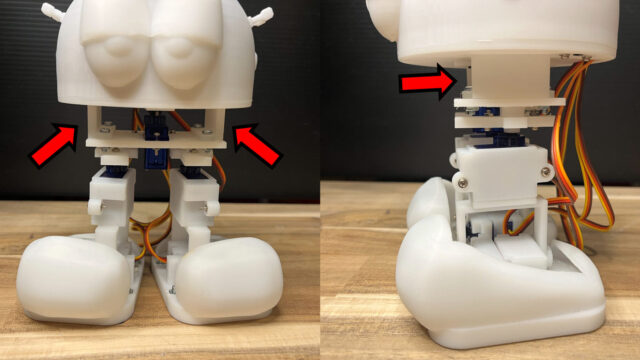
1. Large rattling at each movement point, especially the head
First, the biggest problem. The previous article examined and improved on jittering, but it still occurred rarely. The main cause of this problem was that the servo motor and servo horn are fixed only by the axis of the small servo motor, which tends to flex and vibrate easily. The head, in particular, is heavier and therefore more prone to jittering.
2. Small and fragile decorations
I had put various decorations on my robots, but they were all small and fragile.
3. Insufficient fixation of internal parts
Internal parts were also inadequately fixed.
4. Some parts are difficult to print and not strong enough
Some parts had a lot of support parts made when printing with a 3D printer, and it was very difficult to remove the support material. Also, some parts were not strong enough and could be easily broken, so I had to reinforce them.
5. Difficult to assemble
Partially related to 4 above, there were some parts that were very difficult to assemble. I want to make assembly as easy as possible.
6. Difficult to remove the head
The head cover was designed with a twist-lock mechanism that is turned and secured, but it is somewhat difficult to use and needs to be improved.
I will fix these in Ver.2.
Design of Ver.2
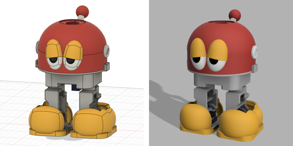
Here is Ver. 2, which solves the six problems in Ver. 1! (Figure 3)
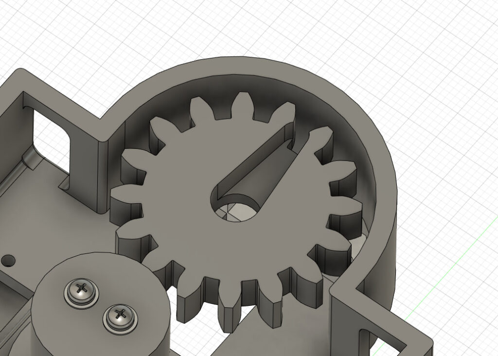
In this case, I introduced gears in some parts (Figure 4) to simplify the placement and reduce rattling.
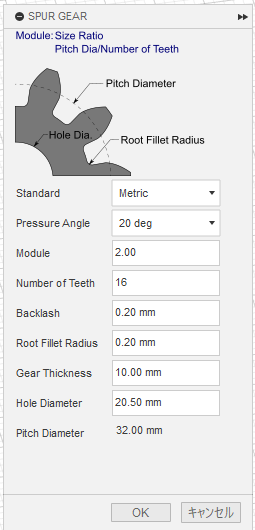
The gears were created using Spur Gear, which is available in Fusion360. (Figure 5)
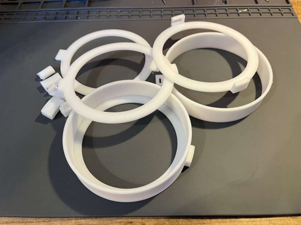
I also tried several times to find good dimensions for the twist-lock mechanism of the head cover. (Figure 6)
Print Ver. 2
The next step is printing.
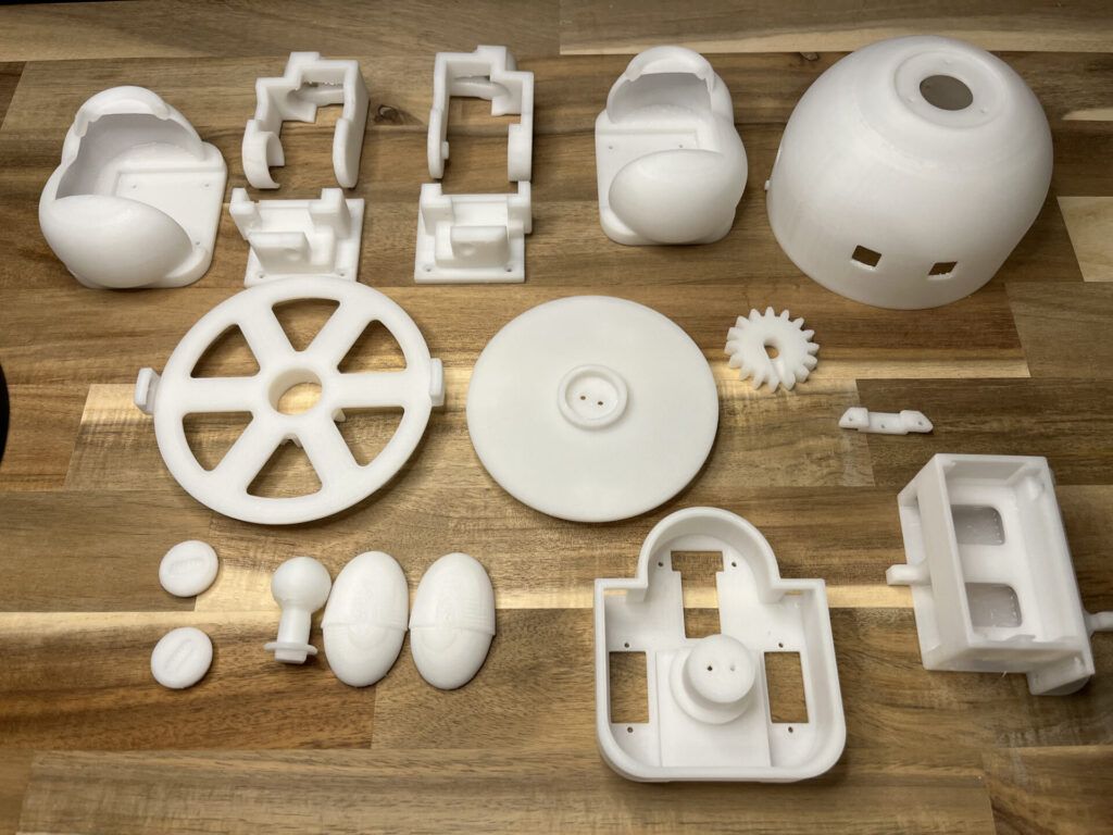
We printed all the parts of this Ver.2 (Fig. 7).
The 3D printer is Zortrax M200 Plus and the filament is Z-HIPS.
Compared to Ver.1, both printing and removal of supports are much easier.
Zortrax M200 Plus↓
eBay: https://ebay.us/5kbqtI
Now I will start the assembly of Ver.2 in the next article!
For the latest status, check here.