Making an Eye Module for Robots! Easy to create with 3D printer
Toon Robotics is supported by its audience. When you purchase through links on my site, I may earn an affiliate commision.
Let’s make robot eyes!
Eyes are important for facial expressions and communication. It is cute when animals or robots look around. I would like to create “eyes” for robots.
What I created this time was not a camera or sensor, but an “eyeball” that moves like an animated character.
There are robots that reproduce the movements of animals and fictional creatures.
Such a field is called “animatronics.”
In this context, there are people who are creating devices that realize moving eyeballs.
While these devices are realistic, they are difficult to create and control because of the large number of moving parts.
So I limit the functionality. I have created a device that can 3D print almost all of its parts and is easy to assemble. The one I created this time uses only two servomotors, so it is easy to control and maintain.
Let’s make an eye module with a 3D printer!
You can print almost all parts of this eye module with a 3D printer.
STL files for the required parts are available on the following website.
Cults 3D: https://cults3d.com/en/3d-model/gadget/simple-eye-module-for-robots
Quick preview video on YouTube
Preparation
The following is a list of what you need.
- All printed STL file parts of the Simple Eye Module
- Servo Motor SG90 x 2
- M2 8mm screw x 2
- M2 10mm screw x 4
- M2 15mm or more screw x 8
- M2 Nut x 14
- Microcontroller board (Arduino, etc.)
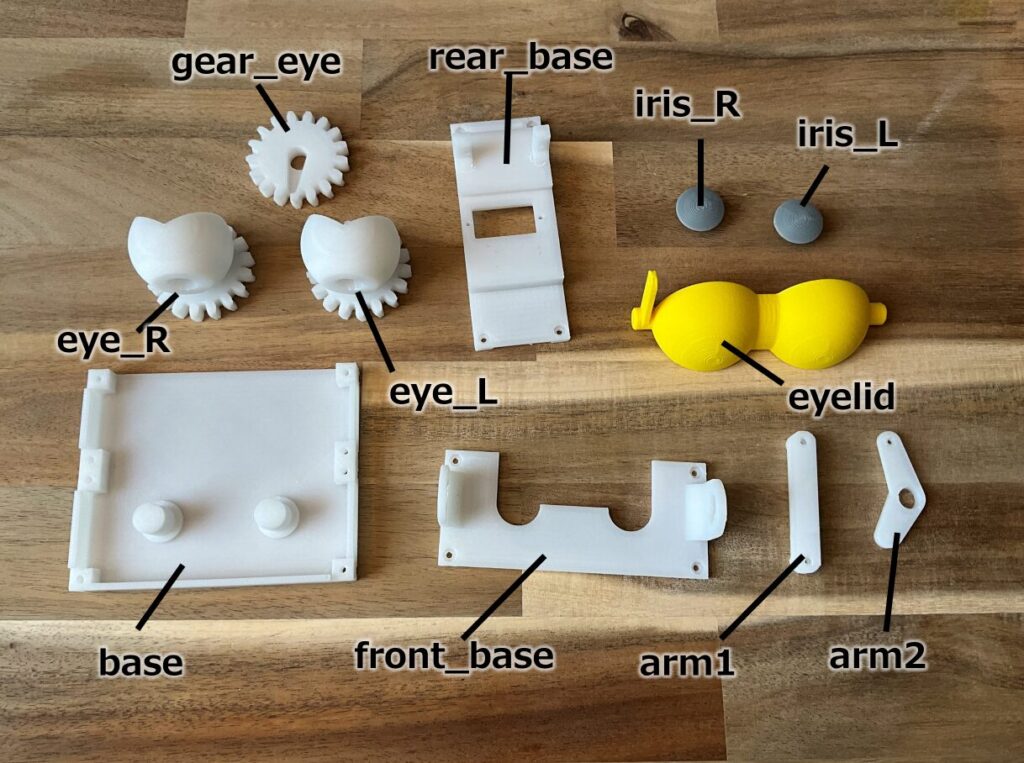
The STL files included in the Simple Eye Module for Robots are as follows.
- arm1.stl
- arm2.stl
- base.stl
- eye_L.stl
- eye_R.stl
- eyelid.stl
- front_base.stl
- gear_eye.stl
- iris_L.stl
- iris_R.stl
- rear_base.stl
We should print these using a 3D printer.
Two SG90 servo motors are also required.
SG90 on eBay AliExpress
Screws and nuts are also required.
You can use any microcontroller board that can control servo motors, such as Raspberry Pi, but this article assumes the use of an Arduino.
Arduino on eBay
Raspberry Pi on eBay
How to make an eye module
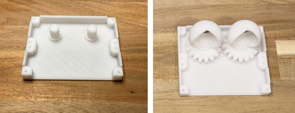
First, print all the parts. Figure 1 shows the printed parts.
Next, let’s align both servo motors SG90 to the 90-degree position; on the Arduino, you can set them to 90 degrees with the following code. When using the following code, connect the signal line of the servomotor to pin 11; for SG90, connect GND to brown, Vcc to red, and the signal line to the yellow line.
#include <Servo.h>
Servo servo;
void setup() {
servo.attach(11);
}
void loop() {
servo.write(90);
delay(1000);
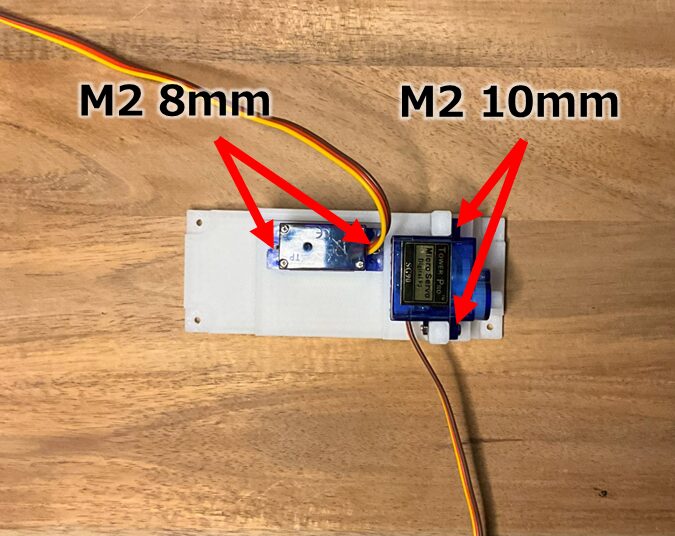
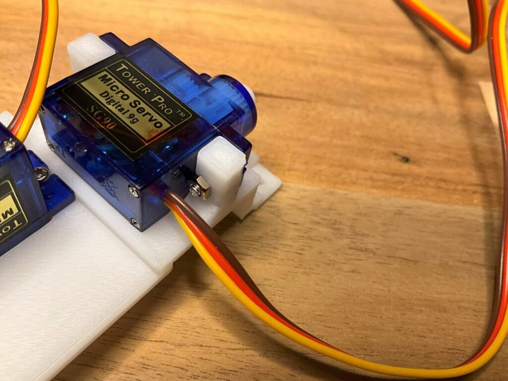
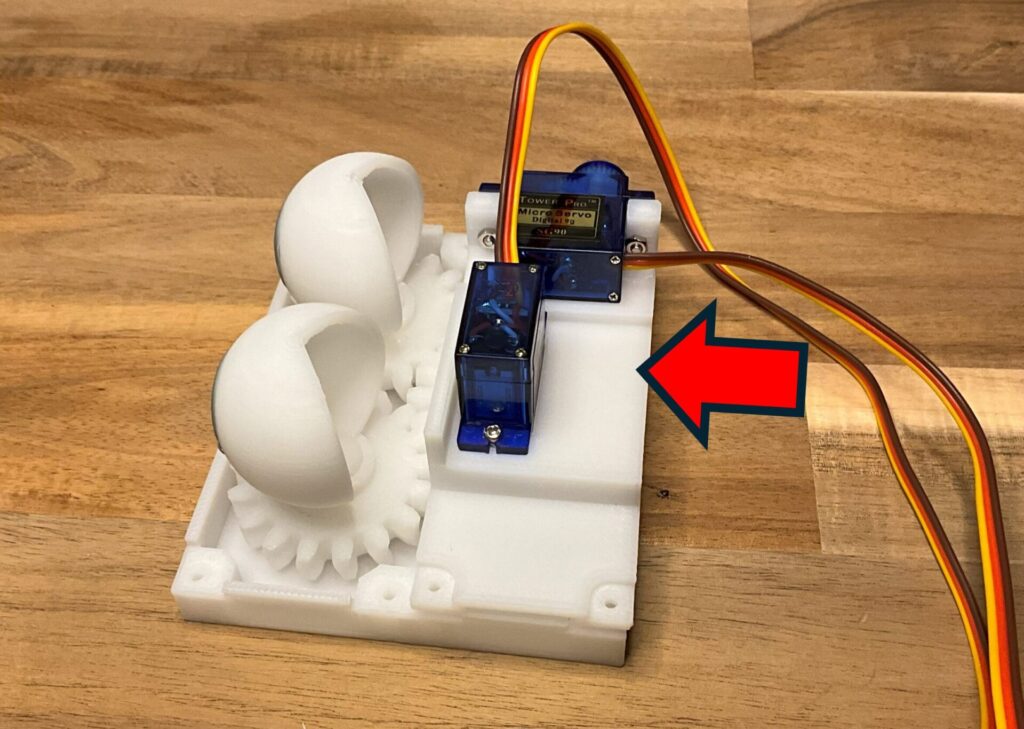
}Once the servo positions are at 90 degrees, attach both of them to the rear_base (Figures 2, 3).
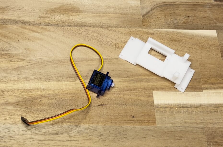
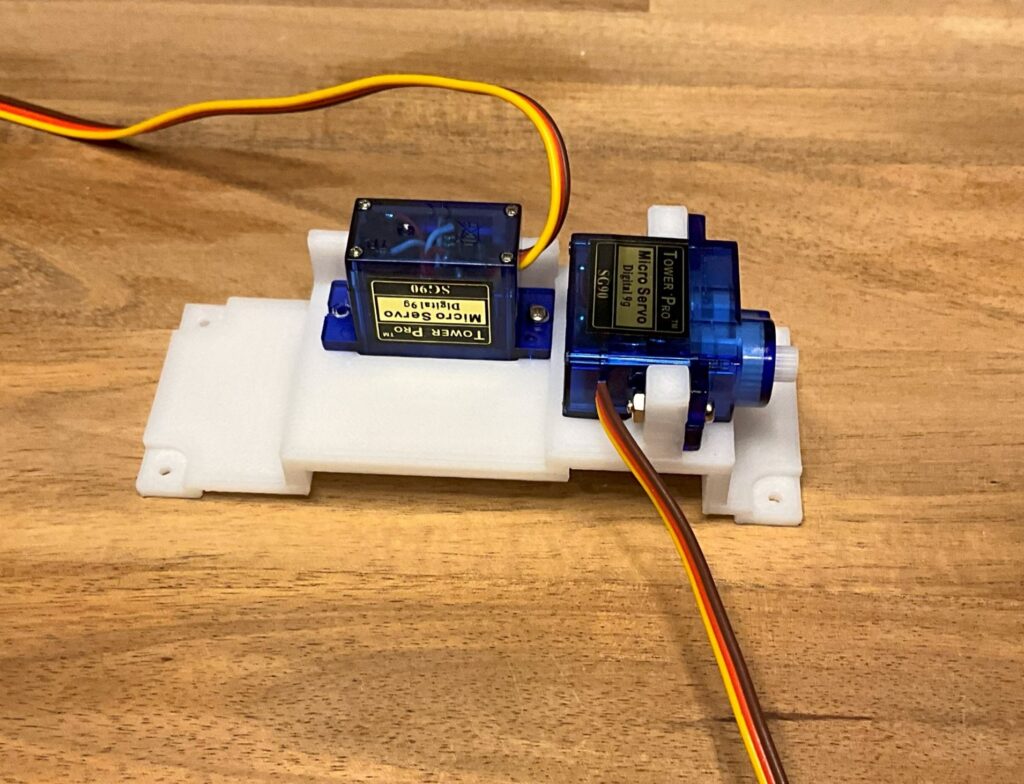
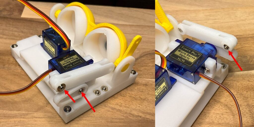
Use two M2 8mm and two M2 10mm screws (Figure 4). Fasten from the opposite side with M2 nuts (Figures 5 and 6). Please pay attention to the orientation of the servo.
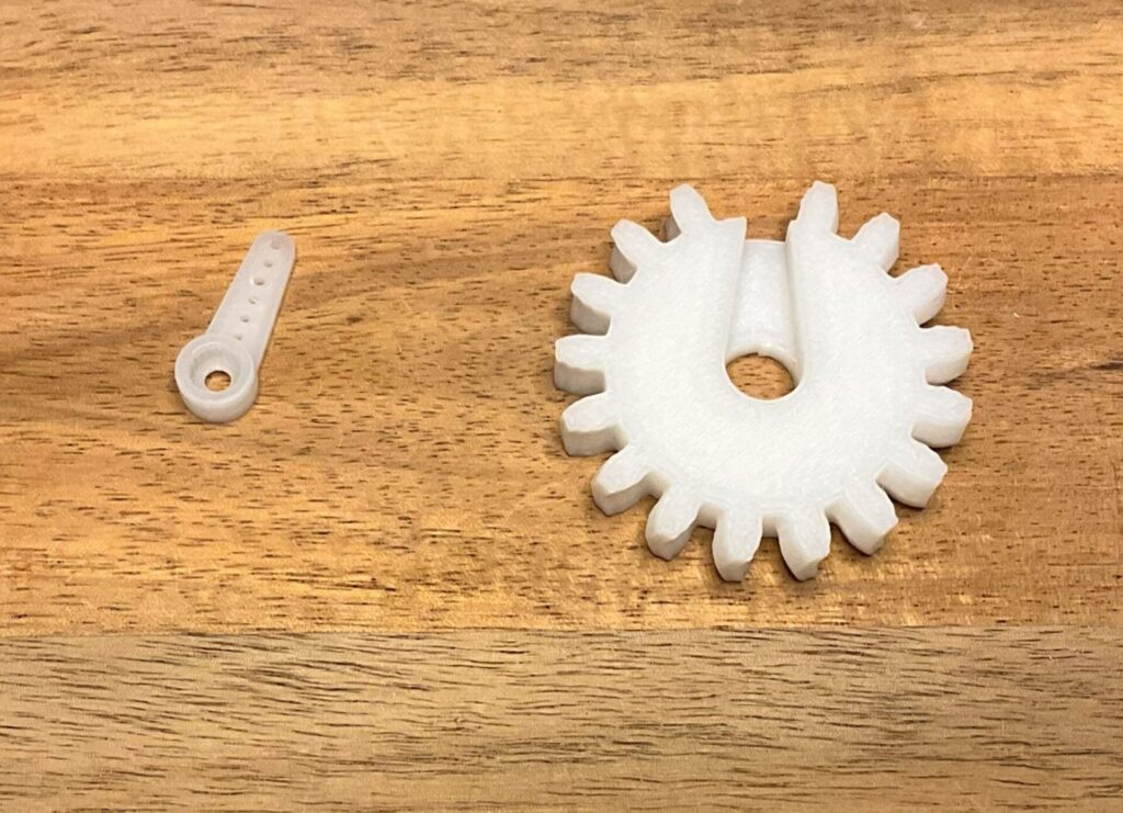
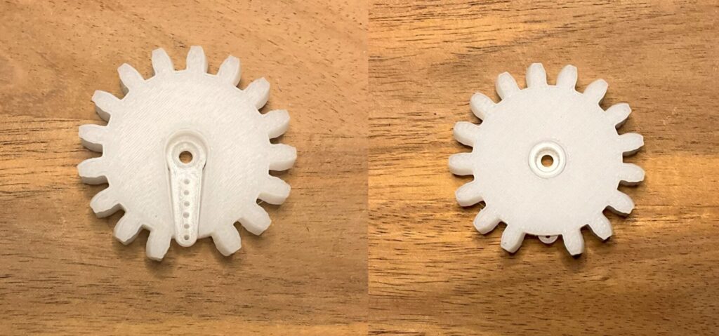
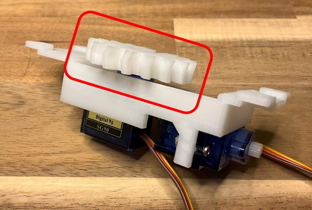
Attach the gear: fit the servo horn supplied with the SG90 into the gear_eye (Figures 7 and 8). Please pay attention to the orientation.
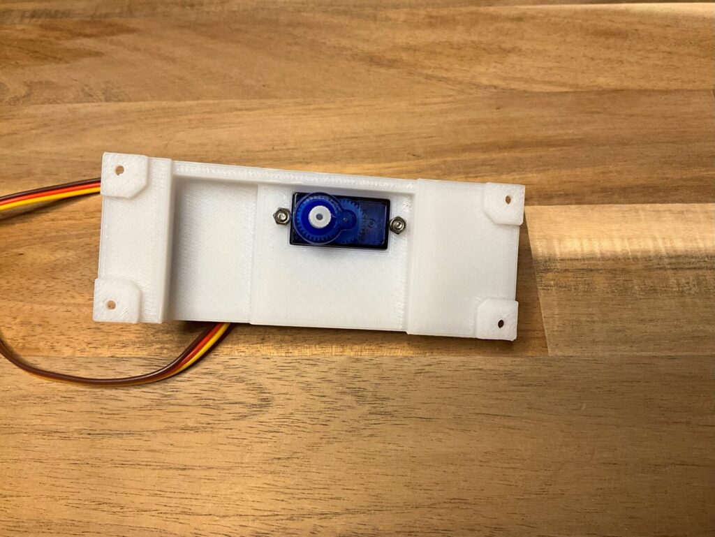
Fix the servo horn to the servo motor SG90, which is mounted downward on the rear_base.
Be careful of the orientation of this as well. Install it referring to Figure 9 and fix it to SG90 with the provided screws. Attach the servo horn so that the tip of the servo horn is toward the rear.
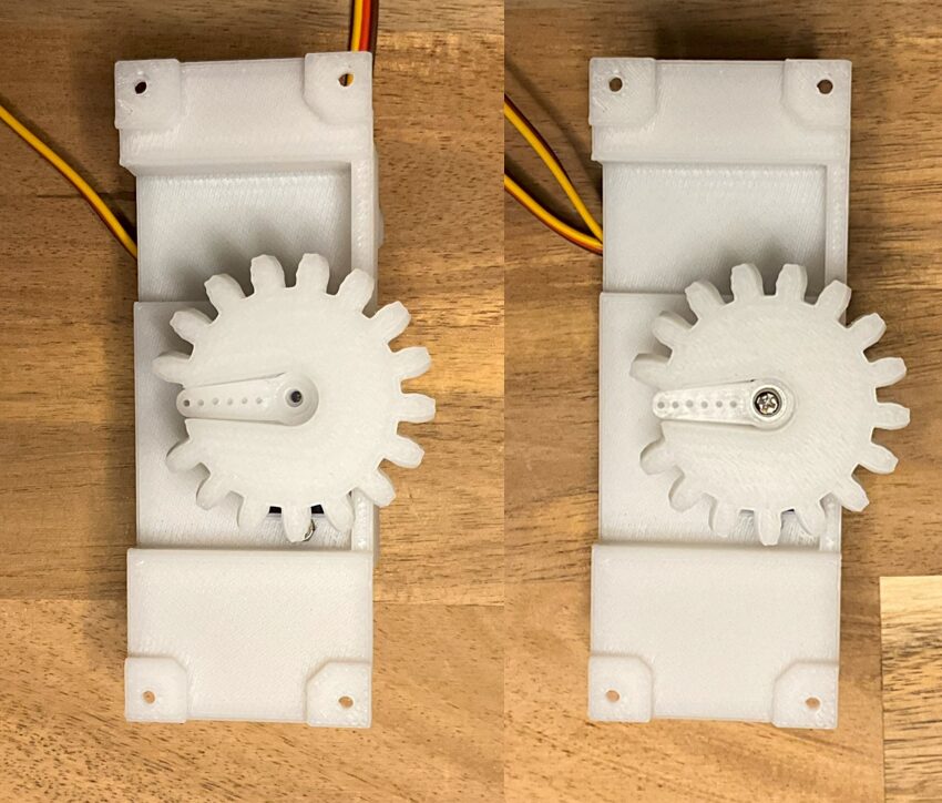
Secure SG90 with the provided screws (right).
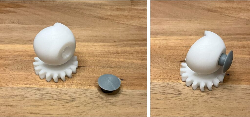
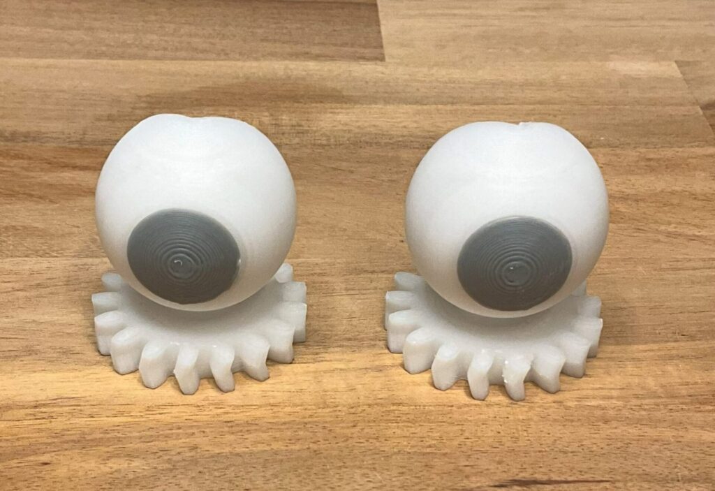
Now, let’s assemble the eye parts: fit the eye_L and iris_L, and eye_R and iris_R into their respective positions (Figures 10 and 11). If they are too tight or too loose, file them down or use adhesives to adjust them.
Next, attach the assembled eye parts to the base.
Fit eye_L and eye_R into each of the two columns of the base (Figure 12).
Then install the rear_base so that the gear teeth mesh with the eye parts (Figure 13). Insert the gear from the back side of the base so that the gears engage (Figure 14).
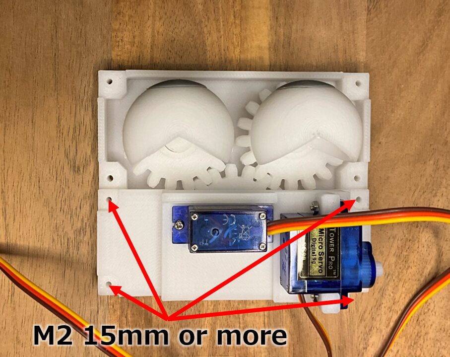
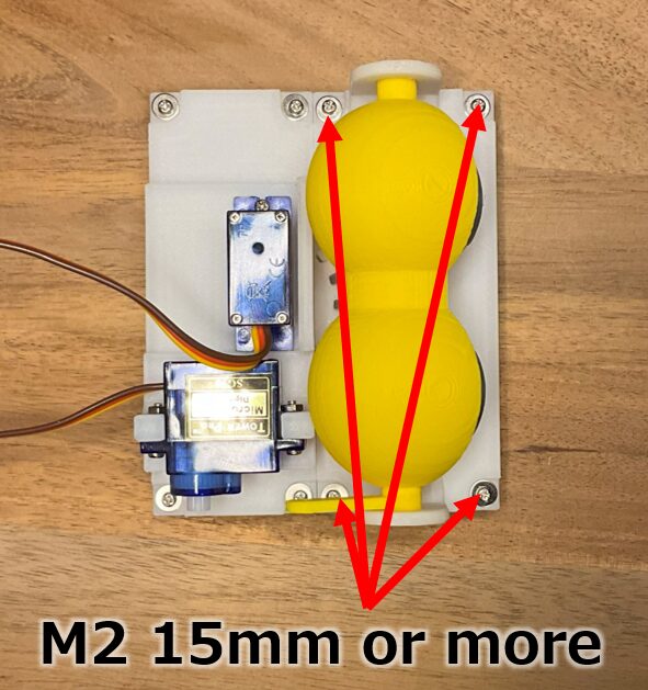
After inserting the rear_base so that the gears mesh with each other, fix it in 4 places with M2 15mm or longer screws. From the back side, fix with M2 nuts (Figure 15).
Also, as described below, it is possible to prepare longer screws, make your own fixing parts to match the dimensions, and fix them to the fixing parts.
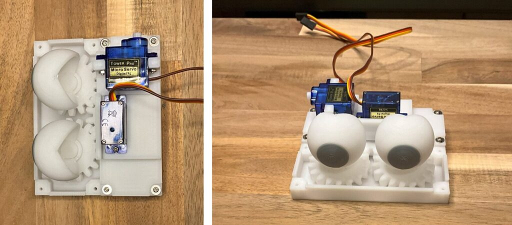
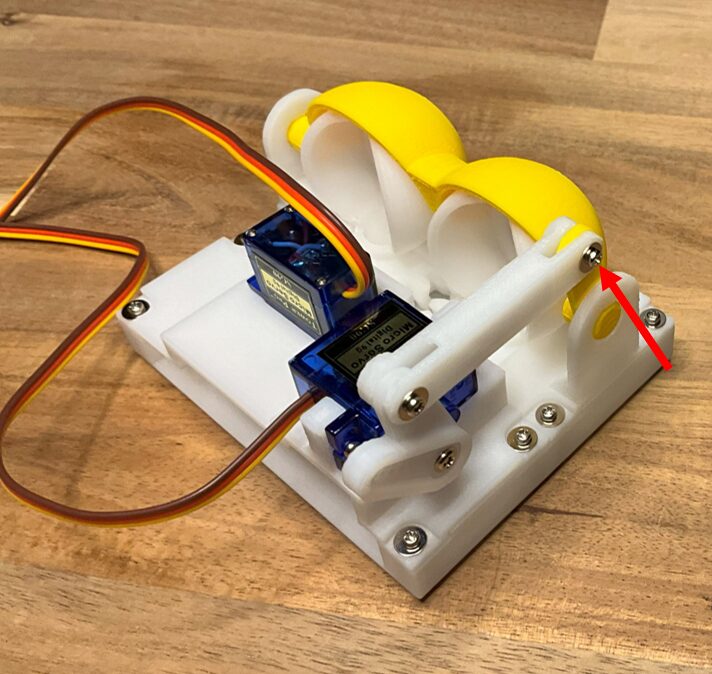
When assembled to this point, it looks like Figure 16.
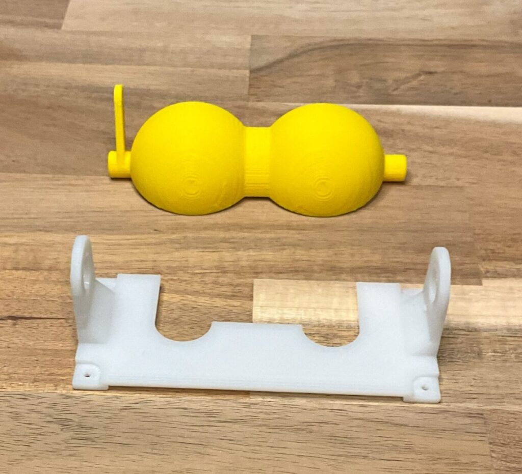
Now, let’s continue with the eyelid assembly. Prepare the eyelid and front_base (Figure 17).
First, align the eyelid and front_base as shown in Figure 18. The eyelid can still come off if shifted slightly, even in the state shown in Figure 18.
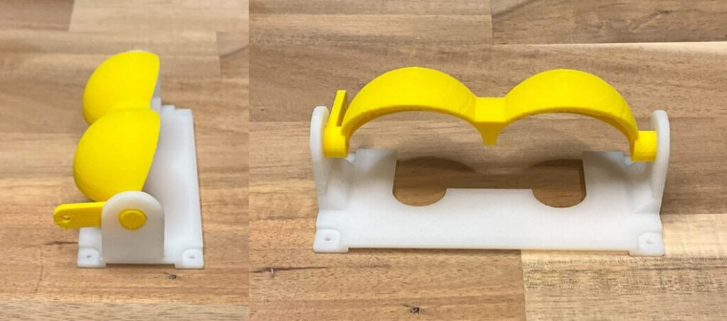
Insert this from the front of the base (Figure 19). If it is a little tight, you may need to press it in firmly. Once firmly inserted, the eyelid should not come off.
Once this is done, fix the part with screws M2 15mm or longer (Figure 20). From the back side, use M2 nuts or other means to secure it.
Attach the arm to move the eyelid. Align the arm2 with the servo horn supplied with SG90 as shown in Figure 21.
Attach this to the other sideways-facing SG90.
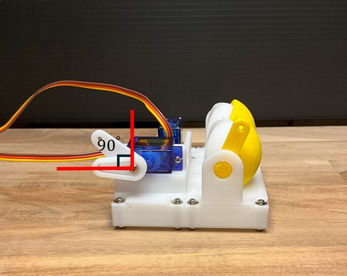
Use the screws provided with the SG90 to fix it at this time, ensuring that arm2 is oriented at the angle shown in Figure 22. The tip of the servo horn should be horizontal.
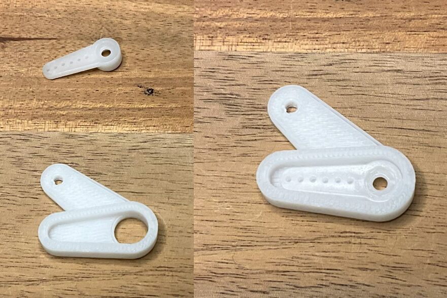
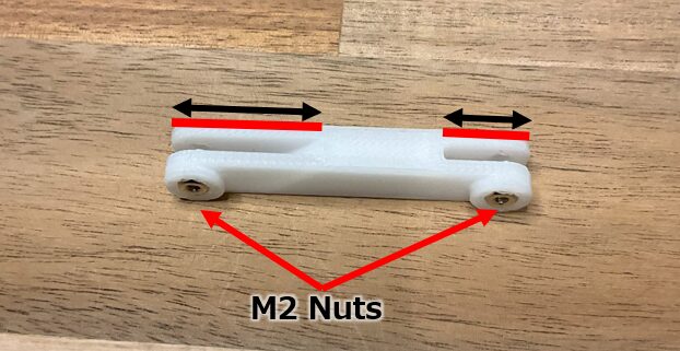
Next, attach arm1. As shown in Figure 23, arm1 has an orientation. Install the one with the deeper cutout on the arm2 side. Moreover, place M2 nuts in both holes, with the nut side facing inward.
Fix the arm part to the servo horns of SG90 fixed earlier, arm1 and arm2, and arm1 and eyelid, for three locations.
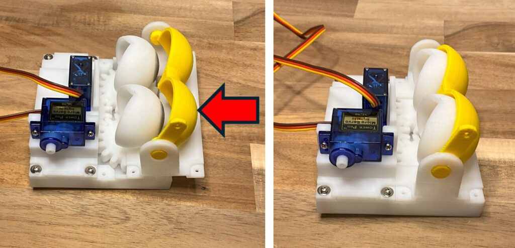
Use 10mm M2 screws to fasten arm1 and arm2 (Figure 24). The arm1 and arm2 should move smoothly and should not be over-tightened.
Similarly, fix the eyelid and arm1 with M2 10 mm screws. Do not tighten this one too tightly (Figure 25).
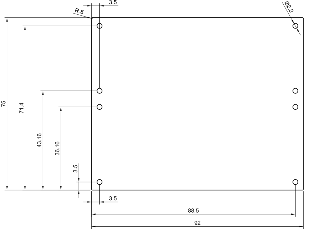
The dimensions shown in Figure 26 define the fixing positions of the base and the part1 and part2. If you make another fixing part with the same dimension, you can fix it with a long M2 screw (Figure 27).
Performance Test
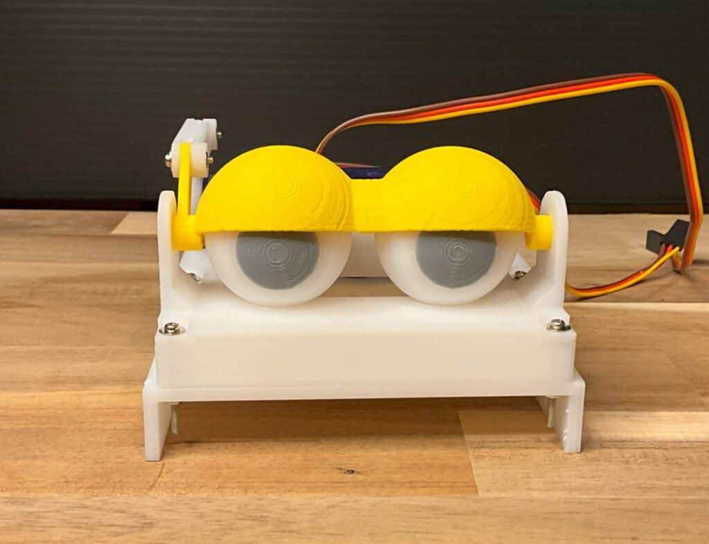
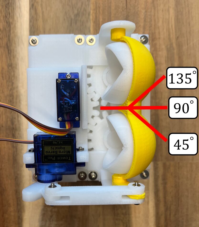
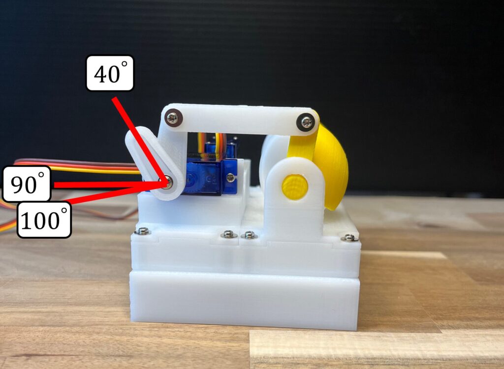
Now let’s actually move it. This module has a horizontal servo motor SG90 that moves the eyeballs from 45° to 135° (Figure 28) and a servomotor that moves the eyelids from 40° to 100° (Figure 29). Since it varies slightly depending on the misalignment at the time of installation, please adjust the angle for your use.
Here is a sample program for Arduino. (You can also get it from here. Github)
#include <Servo.h>

// Servo
Servo servo_eyelid, servo_eye;

// Servo angles
int eyelid_min = 40, eyelid_max = 100;
int eye_min = 45, eye_max = 135;

// Current time and previous time
unsigned long prev = 0, current = 0, elapsed = 0;

// Time interval
unsigned long interval_milli_sec = 150;
unsigned long eye_interval_milli_sec = 1000;
unsigned long current_eye_interval = 0;
unsigned long eyelid_interval_milli_sec = 3000;
unsigned long current_eyelid_interval = 0;

int eyelid_basepos = eyelid_max;
int eye_motion_number = 0;
int blink_motion_number = 0;

void setup() {

  servo_eye.attach(11);
  servo_eyelid.attach(13);

}

void loop() {

  // Get the current time in milliseconds
  current = millis();

  // Calculate the time elapsed since the previous loop iteration
  elapsed = (current - prev);

  // Execute control of the eye and eyelid servos each time interval_milli_sec elapses
  if(elapsed >= interval_milli_sec){

    ///servo for eyes
    current_eye_interval += elapsed;
    if(current_eye_interval >= eye_interval_milli_sec){
      int angle = 90;
      if(eye_motion_number == 0){
        angle = eye_min;
        eye_motion_number++;
      }else if(eye_motion_number == 1){
        angle = eye_max;
        eye_motion_number++;
      }else{
        eye_motion_number = 0;
      }
      servo_eye.write(angle);

      current_eye_interval = 0;
    }

    ///servo for eyelid
    current_eyelid_interval += elapsed;
    if(blink_motion_number == 1){
      servo_eyelid.write(eyelid_basepos);
      blink_motion_number = 0;
    }
    if(current_eyelid_interval >= eyelid_interval_milli_sec){

      if(blink_motion_number == 0){
        servo_eyelid.write(eyelid_min);
        blink_motion_number++;
      }

      current_eyelid_interval = 0;
    }

    prev = current;
  }

}
You should wire it as shown in Figure 30.
Connect the horizontal servo motor that moves the eyeballs to pin 11 and the one that moves the eyelids to pin 13. This is an example of connecting to an Arduino Leonardo, but for another Arduino, you can use any pin that supports PWM. If you want to change the pin, change the pin number of attach() in setup().
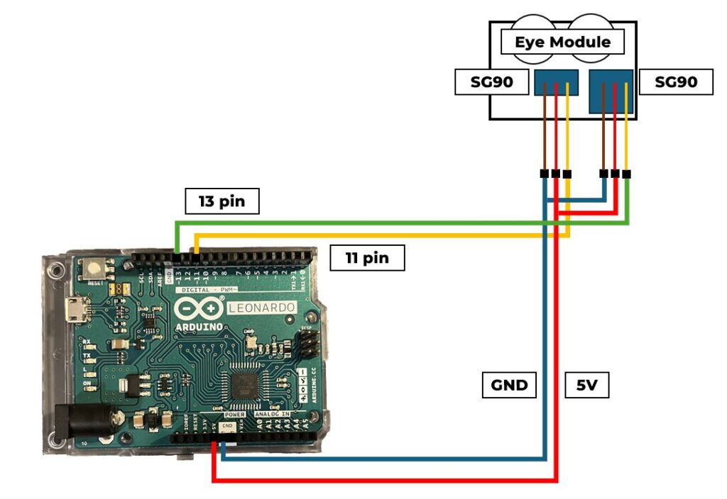
It also supports the use of boards other than Arduino (such as Raspberry Pi, M5Stack).
For the latest status, check here.